Structure improved magnetic pump

A technology of structural improvement and magnetic pump, which is applied to pumps, parts of pumping devices for elastic fluids, pump devices, etc., can solve problems such as uneven material, medium leakage, and deteriorating working environment, and achieve enhanced anti-dry wear performance, improved corrosion resistance, and improved operational safety

Inactive Publication Date: 2017-01-04
KUNSHAN JIANGJINCHANG ANTI DRY FRICTION MAGNETIC DRIVE PUMP
View PDF7 Cites 1 Cited by
  • Summary
  • Abstract
  • Description
  • Claims
  • Application Information

AI Technical Summary

Problems solved by technology

The cumulative effect of these times will lead to premature wear of the bearings, resulting in the pump shaft being seriously deviated from the center of rotation, the internal magnetic rotor and the isolation sleeve will be rubbed, and the isolation sleeve will be worn through quickly and high heat will be generated, resulting in leakage of the medium, which is toxic, flammable and explosive. and other substances spread, and even cause major disasters
[0003] Due to the uneven material of the impeller, the accumulation of blank defects, machining errors, assembly errors, etc., as well as the asymmetric geometric shape in the design, etc., the mass distribution of the impeller is uneven and a certain eccentricity is formed. When the impeller rotates, The unbalanced centrifugal inertial force will cause the pump to generate vibration and noise. Poor dynamic balance will reduce the expected service life of the equipment, especially in the early damage of the bearing, shorten the maintenance cycle of the equipment, increase the maintenance cost of the equipment, and affect the product quality. deterioration of the working environment, etc.

Method used


Image

  • Structure improved magnetic pump
  • Structure improved magnetic pump
  • Structure improved magnetic pump

Examples


Embodiment 1

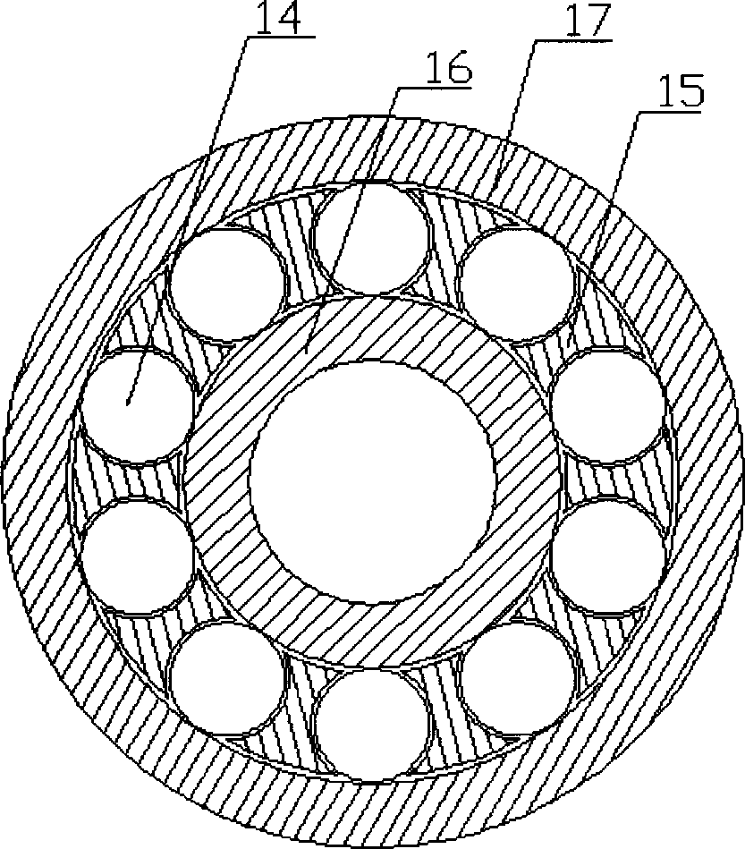
[0012] Embodiment 1: A magnetic pump with improved structure, including a pump body 1, a pump cover 3, a pump shaft 7, an impeller 2, an inner magnetic rotor 5, an outer magnetic rotor 6 and a spacer sleeve 4, and the inner magnetic rotor 5 is fixedly mounted on the pump The shaft end of the shaft 7, the outer magnetic rotor 6 is installed on the shaft end of the motor, the spacer sleeve 4 is set between the inner magnetic rotor 5 and the outer magnetic rotor 6, the spacer sleeve 4 and the pump cover 3 are sealed and fixedly connected, the pump body 1 and the pump cover 3 are tightly connected, the pump body 1, the pump cover 3, and the isolation sleeve 4 are closed to form a pump chamber. When the magnetic pump is working, the outer magnetic rotor 6 is driven by the external driving force to rotate, and the gap between the outer magnetic rotor 6 and the inner magnetic rotor 5 The inner magnetic rotor 5 is driven to rotate by magnetic force, and the inner magnetic rotor 5 drive...

Embodiment 2

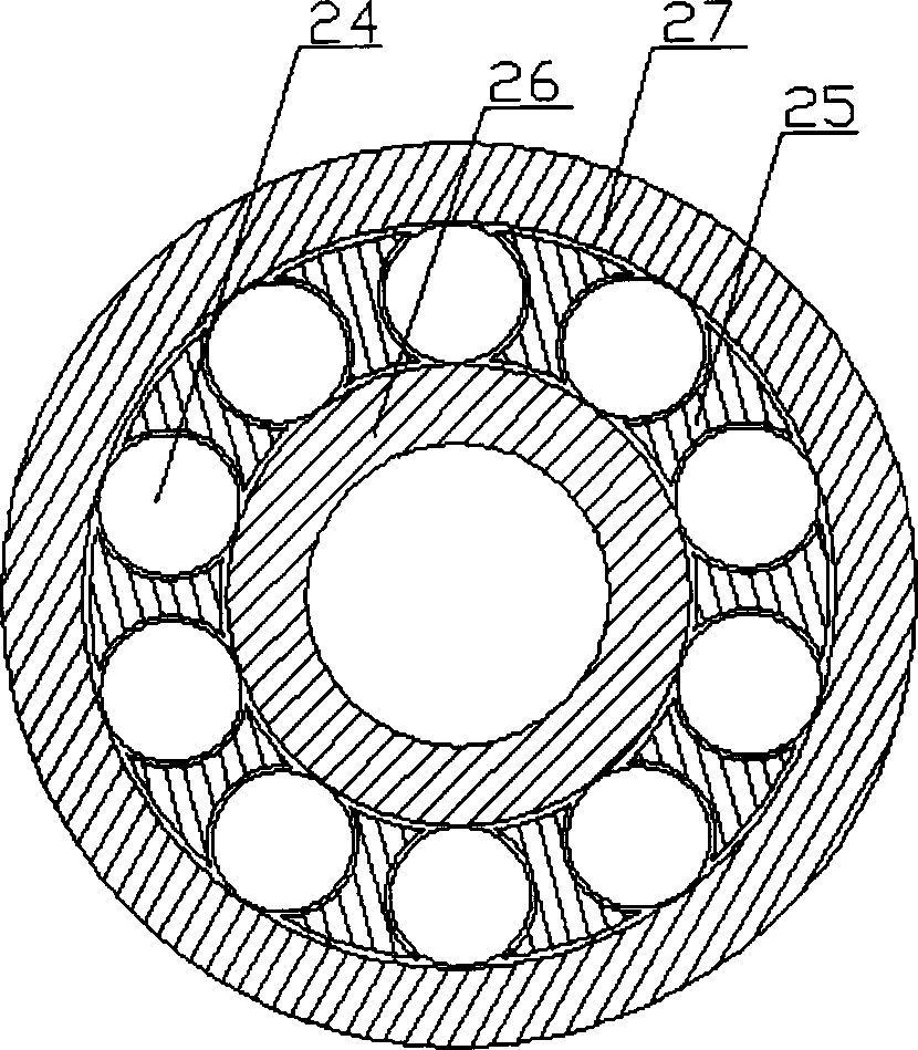
[0017] Embodiment 2: A magnetic pump with improved structure, including a pump body 1, a pump cover 3, a pump shaft 7, an impeller 2, an inner magnetic rotor 5, an outer magnetic rotor 6 and a spacer sleeve 4, and the inner magnetic rotor 5 is fixedly mounted on the pump The shaft end of the shaft 7, the outer magnetic rotor 6 is installed on the shaft end of the motor, the spacer sleeve 4 is set between the inner magnetic rotor 5 and the outer magnetic rotor 6, the spacer sleeve 4 and the pump cover 3 are sealed and fixedly connected, the pump body 1 and the pump cover 3 are tightly connected, the pump body 1, the pump cover 3, and the isolation sleeve 4 are closed to form a pump chamber. When the magnetic pump is working, the outer magnetic rotor 6 is driven by the external driving force to rotate, and the gap between the outer magnetic rotor 6 and the inner magnetic rotor 5 The inner magnetic rotor 5 is driven to rotate by magnetic force, and the inner magnetic rotor 5 drive...


PUM


Abstract

The invention relates to a structure improved magnetic pump. A pump shaft (7) and an impeller (2) are mounted by being supported through a first radial contact bearing (9), a second radial contact bearing (11) and a second axial ball bearing (10) in a pump chamber, and a first axial ball bearing (8) is mounted between the inner wall of the pump chamber and an inner magnetic rotor (5) in a matched manner, the magnetic pump of the structure can effectively control poor dynamic balance of the impeller (2) and the axial movement of the pump shaft (7) and the impeller (2) to greatly reduce heat generated by friction, and can idle in a certain period of time in the absence and zero flow of pumping fluid to enhance the anti-dry grinding performance of the magnetic pump so as to improve the safe operation of the magnetic pump, and parts in the pump chamber are made of corrosion-resistant materials to improve the corrosion resistance of the magnetic pump.

Description

technical field [0001] The invention relates to a magnetic pump, in particular to a magnetic pump with improved structure. Background technique [0002] The magnetic pump is different from the traditional sealed pump. The motor shaft and the pump shaft are not directly connected, but the motor shaft drives the outer magnetic rotor to rotate. The outer magnetic rotor and the inner magnetic rotor cooperate to drive the inner magnetic rotor to rotate through magnetic force. The rotor drives the pump shaft to rotate, so that the impeller rotor on the pump shaft rotates to work. There is a sealing cavity formed by a spacer sleeve between the inner magnetic rotor and the outer magnetic rotor of the magnetic pump, which seals the pump shaft and the inner magnetic rotor in the sealing cavity. One can prevent the liquid from leaking from the pump shaft end to the outside, and the other can prevent the pump from leaking. The shaft and the inner magnetic rotor are cooled, so there is ...

Claims


Application Information

Patent Timeline
Patent Type & Authority Applications(China)
IPC IPC(8): F04D13/06F04D29/041F04D29/049F04D29/02
Inventor 高涵文高来生
Owner KUNSHAN JIANGJINCHANG ANTI DRY FRICTION MAGNETIC DRIVE PUMP
Why Eureka
Try Eureka