Panel door lock structure

A door lock structure and panel lock technology, which is applied in building locks, building structures, buildings, etc., can solve the problems of not being able to install the lock cylinder cover, reduce production efficiency, time-consuming and process-consuming, and achieve the improvement of production management level and Production efficiency, convenient matching effect

Inactive Publication Date: 2017-01-04
GUANGDONG JINDIAN ATOM LOCK
View PDF7 Cites 1 Cited by
  • Summary
  • Abstract
  • Description
  • Claims
  • Application Information

AI Technical Summary

Problems solved by technology

At present, there are many types and specifications of panel locks. The protective cover of the same lock cylinder can only match the lock hole on one panel, and the universality of the lock accessories is not strong. In the era of online shopping, people's shopping personality is becoming more and more prominent. They often buy accessories from the Internet for DIY. Because the lock accessories are not universal, it is difficult to match the panels and lock cylinder covers produced by different manufacturers, or the keyhole of the panel is too small. The lock cylinder cover cannot be installed, or the lock cylinder cover is too small, and the gap 201 between the lock cylinder cover 3 and the panel lock hole is too large, it is easy to use the gap to pry the door lock with tools, and the gap is too large to affect Beautiful; the second is that the panel locks of different varieties and specifications from the same manufacturer are not matched, which not only consumes time and workmanship in production, increases inventory and models, but also easily causes mistakes. Each batch of products must be determined according to the sales situation, which is inconvenient. Warehouse statistics, which increases the difficulty of product management, reduces production efficiency, and increases production costs

Method used


Image

  • Panel door lock structure
  • Panel door lock structure
  • Panel door lock structure

Examples


Embodiment Construction

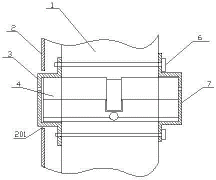
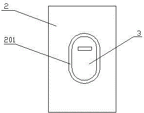
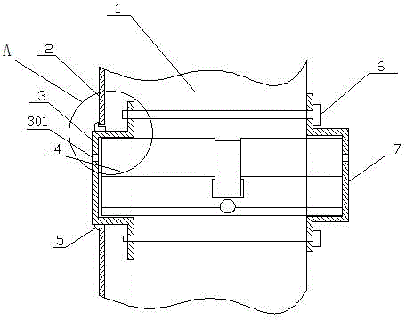
[0015] See image 3 —— Figure 5 , a panel door lock structure, including a panel 2 with a keyhole, a lock cylinder cover 3 with a keyhole 301 and a decorative ring 5, the lock cylinder cover 3 is arranged in the lockhole of the panel 2, and the decoration The ring 5 is sleeved on the lock cylinder cover 3. The decorative ring 5 includes an annular body 501 and an annular cover plate 502 extending radially outward from one end of the body 5. The size of the inner ring of the body 5 is the same as that of the The external dimensions of the lock cylinder cover 3 are consistent, the radial width L of the cover plate 502 is 2.5mm-5mm, and the cover plate 502 of the decorative ring 5 closes the gap between the lock cylinder cover 3 and the panel lock hole. 201 covered.

[0016] When the present invention is installed, the lock cylinder 4 is installed in the door leaf 1, and the front and rear lock cylinder protective covers 3 and 7 are fixed on the front and rear sides of the doo...


PUM


Abstract

The invention discloses a panel door lock structure which comprises a panel equipped with a locking hole and a lock cylinder protective cover and is characterized by comprising a decorative ring, wherein the lock cylinder protective cover is disposed in the locking hole of the panel; and the decorative ring sleeves the lock cylinder protective cover and covers clearance between the lock cylinder protective cover and the panel locking hole. According to the invention, a cover plate of the decorative ring can be used to shield the clearance between the panel locking hole and the lock cylinder protective cover; and based on a minimum lock cylinder size during design, a lock cylinder can be matched with locking holes in all the panels if the radial width of the decorative ring cover plate is larger than the maximum clearance between the lock cylinder and the panel locking holes in the current market. In this way, a manufacturer only needs to produce lock cylinders and matched lock cylinder protective covers of the same specifications so as to solve the problem in the prior art that panels and the lock cylinder protective covers are non-universal; matching can be achieved by consumers more easily; and a production management level and production efficiency of the manufacturer can be increased.

Description

technical field [0001] The invention belongs to locks, in particular to a panel door lock structure. Background technique [0002] Panel locks are widely used in the doors of residential and office buildings because of their better anti-theft and decorative properties. Existing panel locks include a lock cylinder, a panel and a lock cylinder cover, such as figure 1 , figure 2 As shown, during installation, the lock core 4 is first installed in the door leaf 1, then the front and rear lock core shields 3, 7 are installed with bolts 6 on both sides of the door leaf 1 to cover the two ends of the lock core 4, and then the panel 2 is installed on the door leaf 1. On the lock cylinder cover 3, the lock cylinder cover 3 is stretched out from the lock hole on the panel 2. At present, there are many types and specifications of panel locks. The protective cover of the same lock cylinder can only match the lock hole on one panel, and the universality of the lock accessories is not...

Claims


Application Information

Patent Timeline
Patent Type & Authority Applications(China)
IPC IPC(8): E05B15/00
Inventor 雷先鸣
Owner GUANGDONG JINDIAN ATOM LOCK
Why Eureka
Try Eureka