A Calculation Method for Earth Pressure of Retaining Wall in Soft Soil Area
A calculation method and retaining wall technology, applied in construction, artificial island, infrastructure engineering, etc., can solve complex, inaccurate and inconvenient active earth pressure problems, and achieve the effect of simple flow field
- Summary
- Abstract
- Description
- Claims
- Application Information
AI Technical Summary
Problems solved by technology
Method used
Image

Examples
Embodiment 1
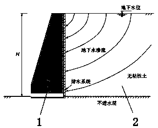
[0057] The structure of the vertical retaining wall considering the seepage conditions is such as figure 1 As shown, since the wall is permeable along the interface between the soil body 2 and the retaining wall 1, all the water reaching the interface can be drained. The soil body is non-viscous and fully saturated under the ground. This condition may occur when continuous heavy rain falls. This condition is critical when the active earth pressure reaches its maximum value. The bottom of the soil layer is an impermeable layer, so all water reaching the retaining soil body will follow the soil and The interface of the structure flows away at a certain time.
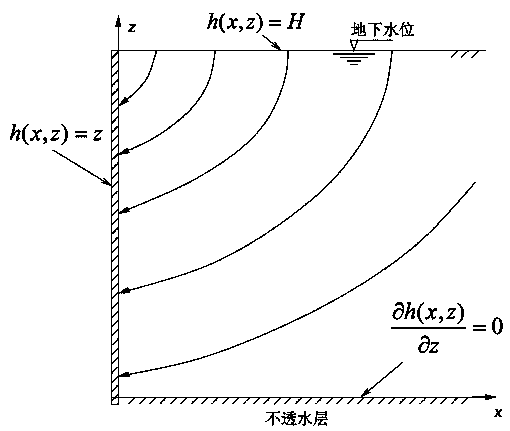
[0058] Establish a closed-form analytical solution of water seepage in the soil, and then use this solution in the Coulomb equation. According to the equation, set the wall displacement enough to make the soil in the active state. There will be a plane failure surface. In this way, the Coulomb-like coefficient of active earth...
Embodiment 2
[0090] Such as Figure 4 As shown, it is assumed that the interface between soil body 2 and retaining wall 1 is completely smooth, and the acting direction of earth pressure is horizontal. When the displacement of retaining wall 1 is sufficient to cause the shear strength of soil body 2 (active state) Change, a failure surface (set as a plane) will be formed. The soil wedge 3 formed by the failure surface is regarded as a rigid body, and the force acting on its boundary is shown in the analysis in the figure.
[0091] Such as Figure 4 In, the weight of the soil wedge is shown in equation 13;
[0092] Formula 13: Where γ sat Is the saturation weight of the soil, H is the height of the wall, and a=cotθ represents the slope of the failure surface.
[0093] Pa is the active earth pressure, N is the normal effective stress, and T is the tangential force acting on the failure surface. Pore water pressure U is the resultant force of pore water pressure acting on the failure surface, U...
Embodiment 3
[0108] Equation 22 shows that the active earth pressure is linearly distributed along the wall, but this is not correct. In order to obtain the correct earth pressure distribution, certain assumptions must be made, such as Figure 7 As shown, when the soil body 2 is in the active state, all the soil in the critical soil wedge 3 are in a plastic equilibrium state, and then the Figure 7 As shown in the analysis.
[0109] The active earth pressure coefficient used to calculate the partial pressure of this part is different from the coefficient obtained in the previous area. The reason for the difference is that the seepage conditions in the local pressure soil wedge are different from the seepage conditions in the full-length area, because they have different distances from the impervious layer at the bottom of the soil layer.
[0110] In the case of local earth pressure, the gravity and pore water pressure along the surface of the soil wedge are respectively W * And U * , Such as fo...
PUM
 Abstract
Description
Claims
Application Information
 - Generate Ideas
- Intellectual Property
- Life Sciences
- Materials
- Tech Scout
- Unparalleled Data Quality
- Higher Quality Content
- 60% Fewer Hallucinations
Browse by: Latest US Patents, China's latest patents, Technical Efficacy Thesaurus, Application Domain, Technology Topic, Popular Technical Reports.
© 2025 PatSnap. All rights reserved.Legal|Privacy policy|Modern Slavery Act Transparency Statement|Sitemap|About US| Contact US: help@patsnap.com