A centrifugal wind wheel and a low-noise backward centrifugal fan including the wind wheel

A centrifugal wind wheel and wind wheel technology, which is applied in the field of centrifugal wind wheel and low-noise backward centrifugal fan, can solve the problems of limited destructive effect and limited noise reduction effect, and achieve the goals of reducing turbulent flow intensity, low manufacturing cost, and improving efficiency Effect

Active Publication Date: 2020-07-14
FANS TECH ELECTRIC CO LTD
View PDF5 Cites 2 Cited by
  • Summary
  • Abstract
  • Description
  • Claims
  • Application Information

AI Technical Summary

Problems solved by technology

This patent can improve the working efficiency of the centrifugal fan, the centrifugal fan including the above-mentioned centrifugal fan, and the air purification equipment including the centrifugal fan, and reduce the noise and power consumption of the centrifugal fan, the centrifugal fan, and the air purification equipment. The large-scale vortex structure in the nearby vortex and backflow component caused by flow separation has limited damage and limited noise reduction effect

Method used


Image

  • A centrifugal wind wheel and a low-noise backward centrifugal fan including the wind wheel
  • A centrifugal wind wheel and a low-noise backward centrifugal fan including the wind wheel
  • A centrifugal wind wheel and a low-noise backward centrifugal fan including the wind wheel

Examples


Embodiment 2

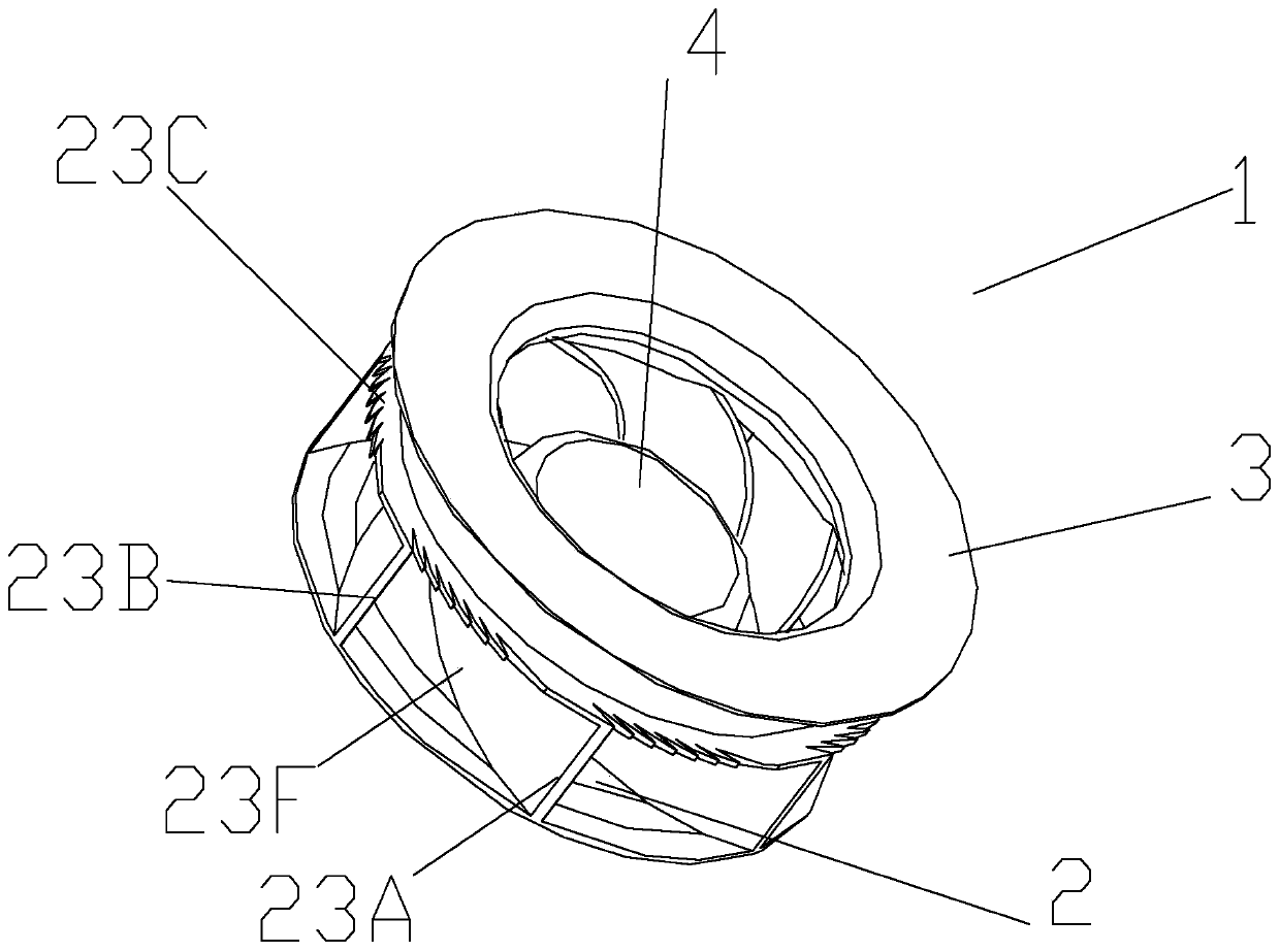
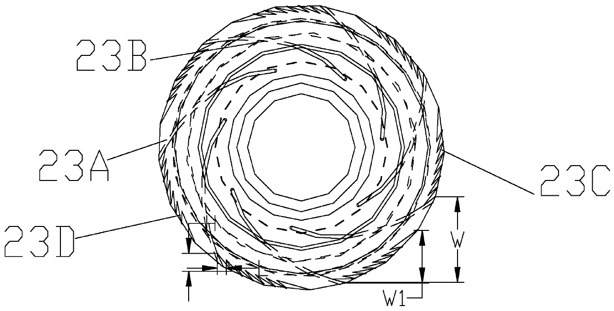
[0047] This embodiment only describes the difference from the above embodiment, and other technical features are the same as the above embodiment. In this embodiment, the arc radii of each of the multi-section arc walls are different, and the arc radii of the multi-section arc walls increase sequentially along the direction from the air inlet end to the air outlet end. arranged in a manner. Preferably in this embodiment, the multiple sections of arc walls include two sections of arc walls. The multi-segment arc walls make the air flow enter the collector 3 and accelerate the gathering towards the end of the collector 3 .

Embodiment 3

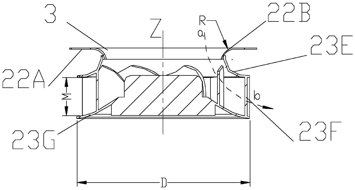
[0049] This embodiment only describes the difference from the above embodiment, and other technical features are the same as the above embodiment. In this embodiment, a vertical wall is provided at the end of the arc wall in the wind guide side wall 22B, the diameter of the vertical wall remains constant along the direction from the air inlet end to the air outlet end, and the inner diameter of the vertical wall The diameter of the ring is smaller than the diameter of the inner ring of the single-segment arc wall or any one of the multi-segment arc walls, and the continuous protruding structure 23C is arranged on the end face of the vertical wall end.

Embodiment 4

[0051] This embodiment only describes the difference from the above embodiment, and other technical features are the same as the above embodiment. In this embodiment, the top wall 22A is an inclined wall, and the top wall 22A slopes downward from the outer ring to the inner ring, that is, the height of the outer ring is placed at the top of the air guiding device, and the inner ring is placed at the top of the air guiding device. below the outer ring.


PUM


Abstract

The invention discloses a centrifugal wind wheel comprising a wind wheel front disc, a wind wheel back disc and wind wheel blades arranged between the wind wheel front disc and the wind wheel back disc. Flow channel regions are jointly defined by the blade pressure surfaces and the blade suction surfaces of the adjacent wind wheel blades and the wind wheel front and back discs, the inner ring of achassis of the wind wheel front disc is bent and extends in the direction far away from the wind wheel back disc along the axial direction to form a front disc side wall, a front disc air inlet is formed in the front disc side wall, the circumferential edge of one or two of the wind wheel front disc or the wind wheel back disc is provided with a plurality of sets of continuous convex structures,and each set of continuous convex structure includes a plurality of evenly-spaced convex structures. The continuous convex structures can destroy the eddy current generated by flow separation near outlets of the flow channel regions and large vortex structures in reflux components, a series of small vortexes are formed, and the amplitude of the eddy current noise in the fan noise is greatly reduced.

Description

technical field [0001] The invention relates to the field of fans, in particular to a centrifugal wind wheel and a low-noise backward centrifugal fan including the wind wheel. Background technique [0002] In the ventilation industry, backward centrifugal fans are usually used in some occasions where it is necessary to change the flow direction of the fluid medium from the axial direction to the circumferential direction. Generally speaking, when the traditional backward centrifugal fan meets the target performance, the noise will be more prominent, especially in today's increasingly stringent noise requirements for household appliances, the disadvantage of high noise of the backward centrifugal fan is even more unacceptable . For equipment such as air purifiers, it usually uses a backward centrifugal fan to increase ventilation. Air purifiers, as home environment electrical appliances, have increasingly strict noise requirements. The backward centrifugal fan is the main n...

Claims


Application Information

Patent Timeline
Patent Type & Authority Patents(China)
IPC IPC(8): F04D29/28F04D29/66F04D29/68
CPCF04D29/281F04D29/666F04D29/667F04D29/681
Inventor 莫远忠杨涛
Owner FANS TECH ELECTRIC CO LTD
Why Eureka
Try Eureka