
Sleeve-valve-pipe grouting and draining soil-nailing retaining device and construction method thereof

A sleeve valve pipe grouting and construction method technology, which is applied in the direction of foundation structure engineering, construction, sheet pile walls, etc., can solve the problems of reduced drainage effect and low permeability of drainage soil nails, achieve good drainage effect and improve tensile strength Performance, the effect of unimpeded drainage channels

Active Publication Date: 2017-01-04
CHONGQING UNIV
View PDF6 Cites 8 Cited by
  • Summary
  • Abstract
  • Description
  • Claims
  • Application Information

AI Technical Summary

Problems solved by technology

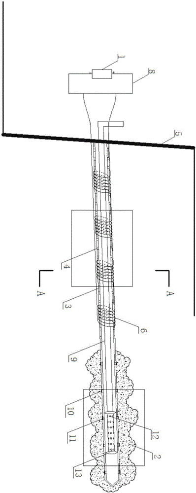
[0004] Purpose of the invention: In order to overcome the above-mentioned deficiencies and defects, and solve the problem that the soil around the soil nails has low permeability and the drainage effect of the drainage soil nails decreases; propose a sleeve valve tube grouting drainage soil nail support device and its construction method

Method used


Image

  • Sleeve-valve-pipe grouting and draining soil-nailing retaining device and construction method thereof
  • Sleeve-valve-pipe grouting and draining soil-nailing retaining device and construction method thereof
  • Sleeve-valve-pipe grouting and draining soil-nailing retaining device and construction method thereof

Examples


Embodiment 1

[0054] A construction method of a sleeve valve pipe grouting drainage soil nail support device, comprising the following steps:

[0055] 1) Investigate and analyze the geological conditions of the slope, conduct engineering geological exploration and design, analyze and determine the design length and diameter of soil nails.

[0056] 2) According to the design length and diameter, make the steel sleeve valve tube 3 in advance:

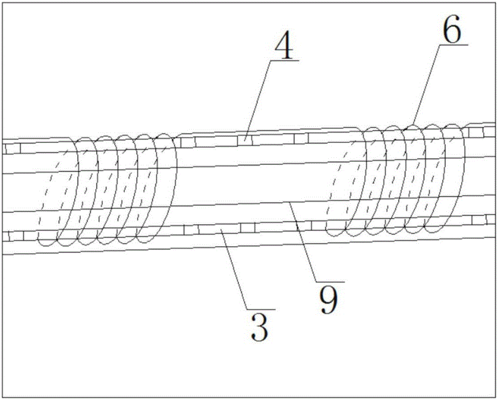
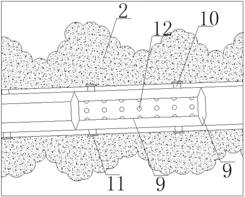
[0057] The steel sleeve valve pipe 3 includes a grouting pipe 9 and an outer pipe. The outer pipe of the steel sleeve valve pipe 3 has several drainage holes 4 and grouting holes 10 . The area with drainage holes 4 is close to the tail of the steel sleeve valve pipe 3 , and the area with grouting holes 10 is close to the head of the steel sleeve valve pipe 3 . The orifice of the grouting hole 10 has a rubber sleeve 11 .

[0058] The inner and outer walls of the outer tube of the steel sleeve valve tube 3 are covered with an epoxy resin protective la...

Embodiment 2

[0076] A construction method of a sleeve valve pipe grouting drainage soil nail support device, comprising the following steps:

[0077] 1) Investigate and analyze the geological conditions of the slope, conduct engineering geological exploration and design, analyze and determine the design length and diameter of soil nails.

[0078] 2) According to the design length and diameter, make the steel sleeve valve tube 3 in advance:

[0079] The steel sleeve valve pipe 3 includes a grouting pipe 9 and an outer pipe. The outer pipe of the steel sleeve valve pipe 3 has several drainage holes 4 and grouting holes 10 . The area with drainage holes 4 is close to the tail of the steel sleeve valve pipe 3 , and the area with grouting holes 10 is close to the head of the steel sleeve valve pipe 3 . The orifice of the grouting hole 10 has a rubber sleeve 11 .

[0080] The inner and outer walls of the outer tube of the steel sleeve valve tube 3 are covered with an epoxy resin protective la...


PUM

PropertyMeasurementUnit
Diameteraaaaaaaaaa
Thicknessaaaaaaaaaa
Diameteraaaaaaaaaa

Abstract

The invention discloses a sleeve-valve-pipe grouting and draining soil-nailing retaining device which is characterized by comprising a steel sleeve valve pipe, a grouting pipe, cement soil, coils and epoxy resin; one end of the steel sleeve valve pipe is opened, the other end of the steel sleeve valve pipe is closed, drain holes and grouting holes are distributed in the surface of the steel sleeve valve pipe on which the coils are wound, and the coils are connected with conducting lines and a high-frequency alternating-current power supply; each of the inner and outer sides of the steel sleeve valve pipe is coated with an epoxy resin protective layer by which the coils are covered; a slope surface is provided with a steel bar wire mesh, and cement slurry is sprayed on the slope surface, so that a cement soil surface layer is formed, and the cement soil covers the steel bar wire mesh; and the steel sleeve valve pipe is grouted at high pressure to form a grouting body. By using the steel sleeve valve pipe with the coils, an electromagnetic field and electromagnetic heating can act in a soil body around an anchor rod, so that the viscosity of water in the soil body is reduced and the draining efficiency is increased under the combined action of the electromagnetic field and a temperature field.

Description

technical field [0001] The invention relates to the technical field of rock-soil anchoring engineering, in particular to a sleeve valve pipe grouting drainage soil nail support device and a construction method thereof. Background technique [0002] The foundation pit is a common engineering form, and the instability and collapse of the slope of the foundation pit will cause serious personnel safety hazards and economic losses. It is one of the most commonly used important methods in the engineering field to reinforce the slope of the foundation pit by using the soil nail support structure; in the foundation pit in the soft soil area with high moisture content in the soil, the shear strength of the soil is relatively low Small; if the water in the soil cannot be drained in time, the risk of foundation pit slope instability or collapse will be greatly increased, so it is necessary to try to drain the water in the soil. For this technical problem, a common method is to arrange...

Claims


Application Information

Patent Timeline
IPC IPC(8): E02D5/74E02D15/04
CPCE02D5/74E02D15/04E02D2250/003
Inventor 吴迪刘汉龙孔纲强周航肖杨
Owner CHONGQING UNIV
Learn More