
Lifting device for aero-engine

A technology of aero-engine and lifting device, applied in the direction of lifting device, lifting frame, etc., can solve the problems of high labor intensity of operators, increase safety production, low work efficiency, etc., achieve the increase of explosion-proof self-locking function, reduce labor intensity, The effect of improving work efficiency

Active Publication Date: 2019-04-02
邯郸市永年区海翔机械厂
View PDF7 Cites 0 Cited by
  • Summary
  • Abstract
  • Description
  • Claims
  • Application Information

AI Technical Summary

Problems solved by technology

However, when the engine is assembled, as the working height increases, the operator needs to use the ladder platform to carry out high-altitude operations. Therefore, the use of the existing general assembly equipment not only has high labor intensity and low work efficiency for the operator, but also has the risk of falling from high altitude. , increasing hidden dangers in production safety

Method used


Image

  • Lifting device for aero-engine
  • Lifting device for aero-engine
  • Lifting device for aero-engine

Examples


Embodiment Construction

[0027] Below in conjunction with accompanying drawing and embodiment the present invention is described in further detail:

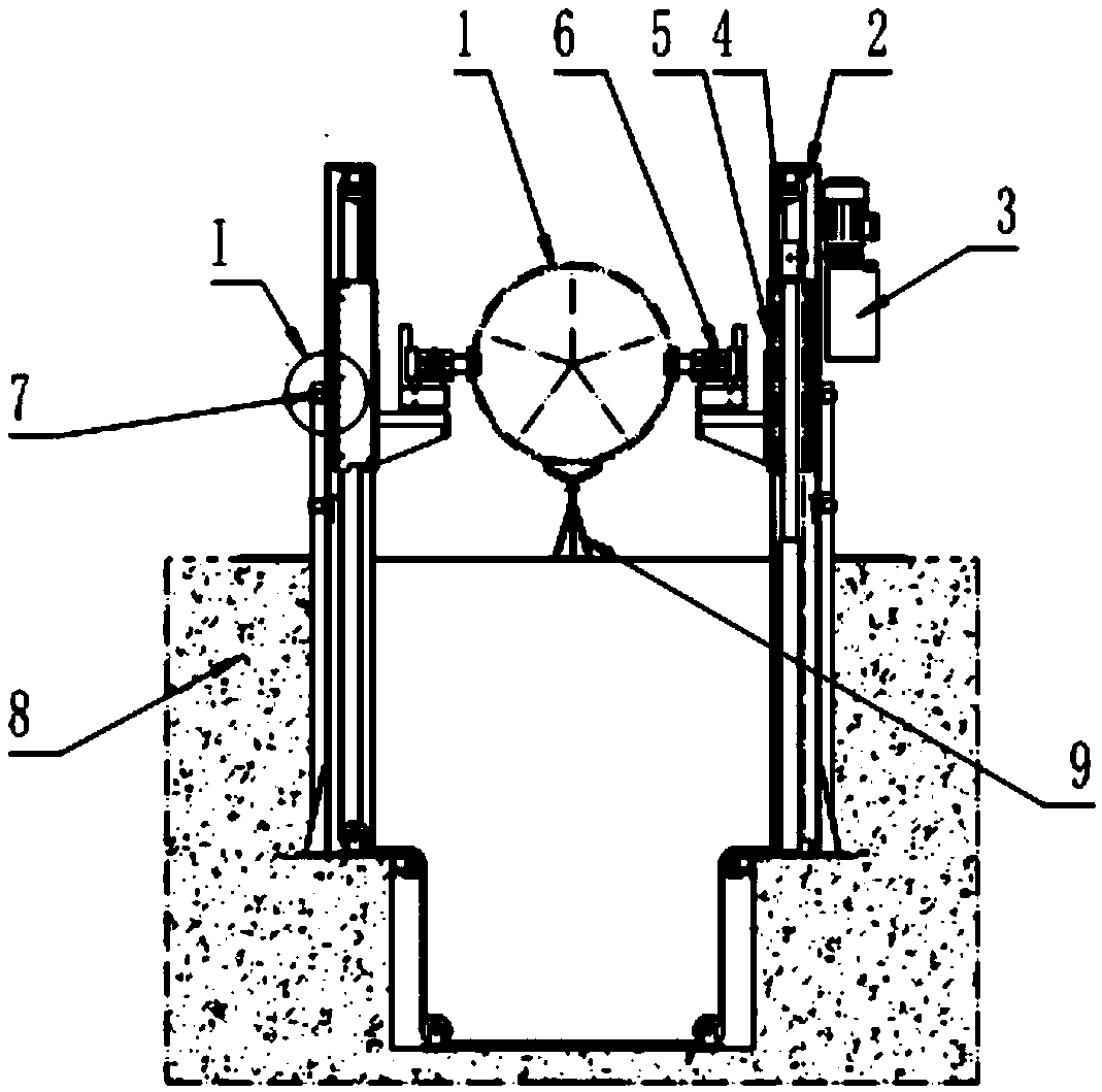
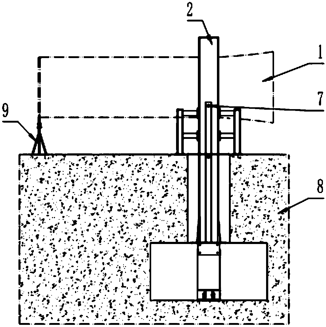
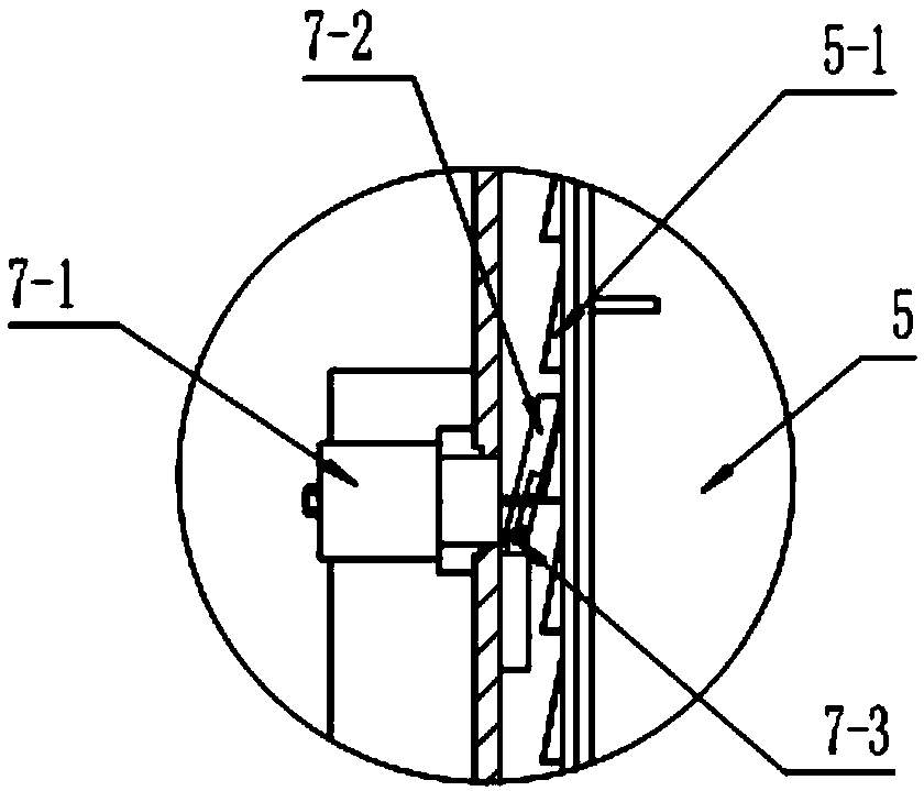
[0028] see figure 1 , figure 2 , Figure 7 , the aero-engine lifting device of the present invention is arranged on the engine assembly groove base 8, including a column 2, a sliding lifting body 5, a lifting drive mechanism 3, an engine support mechanism 6 and an auxiliary support mechanism 9; the column 2 is left and right The symmetrically arranged channel steel structure is equipped with a sliding lifting body 5 on the left column and the right column respectively; Install the engine support mechanism 6; the engine support mechanism 6 is provided with a support shaft 6-1, an axle seat 6-2 and a support assembly 6-3, and the support assembly 6-3 is fixed on the side wall of the sliding lifting body 5, The shaft seat 6-2 is installed on the bracket assembly 6-3, and the support shaft 6-1 is hingedly assembled with the shaft seat 6-2; the auxiliary ...


PUM


Abstract

The invention discloses an aircraft engine lifting device and belongs to the technical field of lifting equipment. The aircraft engine lifting device is arranged on an engine assembly groove pit base body and comprises vertical columns, slidable lifting bodies, a lifting driving mechanism and engine supporting mechanisms. The vertical columns are of U-steel structures arranged symmetrically in a left-right mode. The slidable lifting bodies are assembled on the left vertical column and the right vertical column correspondingly and are controlled to slide along the left vertical column or the right vertical column up and down by the lifting driving mechanism. The engine supporting mechanisms are fixedly installed on the slidable lifting bodies. Each engine supporting mechanism is provided with a supporting shaft, a shaft base and a bracket assembly. The bracket assemblies are fixed to the side walls of the slidable lifting bodies. The shaft bases are installed on the bracket assemblies. The supporting shafts and the shaft bases are assembled in a hinged mode. By means of the aircraft engine lifting device, automatic lifting and air turning functions of an engine are achieved, the labor intensity of operators is relieved, the working efficiency is improved, and in addition, safety production accidents are decreased.

Description

technical field [0001] The invention relates to a lifting device, in particular to a special lifting device suitable for aero-engine maintenance, and belongs to the technical field of lifting equipment. Background technique [0002] In the process of aero-engine maintenance, the final assembly vehicle is an indispensable auxiliary equipment for aero-engine assembly operations. It can provide a basic platform for operators to achieve fixed positioning and overturning operations of the engine. However, when the engine is assembled, as the working height increases, the operator needs to use the ladder platform to carry out high-altitude operations. Therefore, the use of the existing general assembly equipment not only has high labor intensity and low work efficiency for the operator, but also has the risk of falling from high altitude. , Increased hidden dangers in production safety. Contents of the invention [0003] The invention provides an aero-engine lifting device, whi...

Claims


Application Information

Patent Timeline
Patent Type & Authority Patents(China)
IPC IPC(8): B66F7/04B66F7/28
CPCB66F7/04B66F7/28
Inventor 程鑫曹金贤倪伟张哲陶志刚任晓波刘猛
Owner 邯郸市永年区海翔机械厂
Learn More