
Air sac type jack

A jack and airbag-type technology, applied in the direction of lifting devices, etc., can solve the problems of inability to take out the airbag-type jack, damage to operators and property, and high cost of raw materials for seamless pipes

Inactive Publication Date: 2017-01-04
NANTONG TONGRUN AUTO ACCESSORY
View PDF1 Cites 16 Cited by
  • Summary
  • Abstract
  • Description
  • Claims
  • Application Information

AI Technical Summary

Problems solved by technology

However, the inside of the airbag of the airbag jack uses the inner shaft sleeve to limit the position. The processing technology requirements of the inner shaft sleeve are high, and the raw material cost of the seamless pipe used is also high. However, in actual use, due to the weight of the car after being jacked The offset of the airbag jack makes the inner shaft sleeve of the airbag jack extremely easy to get stuck, resulting in unsmooth rise and fall, and vibration; Jack, you need to use other jacks to raise the car before taking it out
It is more likely that the airbag jack will roll over due to the inner shaft sleeve being stuck, causing greater damage to the operator and property

Method used


Image

  • Air sac type jack
  • Air sac type jack
  • Air sac type jack

Examples


Embodiment 1

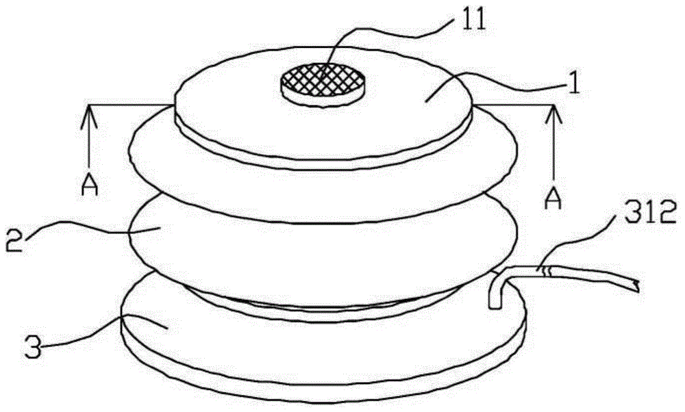
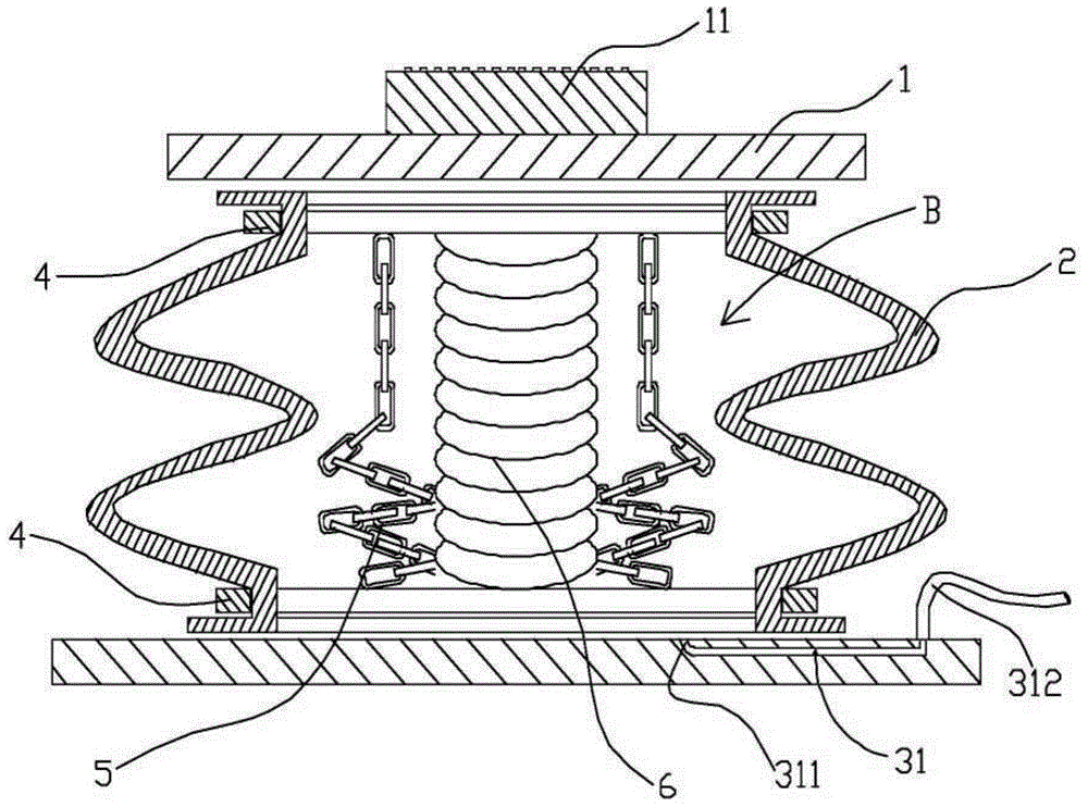
[0022] Figure 1 to Figure 3 A bladder jack according to one embodiment of the present invention is schematically shown. As shown in the figure, the device includes an upper top plate 1, a lower bottom plate 3, a rubber airbag 2 and a flange 4. The interior thus forms a closed pocket B.

[0023] A damping plate 11 is fixed on the upper top plate 1 .

[0024] The lower bottom plate 3 is connected with a high-pressure gas source through an air inlet pipe 312 . The lower bottom plate 3 is provided with an air inlet 31 , and the cavity B is provided with an air outlet 311 . The air inlet pipe 312 communicates with the air outlet 311 through the air inlet 31 .

[0025] A balance limiting device is also provided inside the cavity B.

[0026] In this embodiment, the balance limiting device is three iron chains 5 with the same length. The two ends of the iron chain 5 are fixedly connected with the upper top plate 1 and the lower bottom plate 3 respectively. Three iron chains 5 ...

Embodiment 2

[0030] Figure 4 A bladder jack according to another embodiment of the present invention is schematically shown. The difference from Embodiment 1 is that it also includes a strap 7. As shown in the figure, the strap 7 goes around the upper top plate 1 and is fixedly connected to the lower bottom plate 3 at both ends. In this embodiment, a hole for the strap 7 to pass is provided between the shock absorbing plate 11 and the upper top plate 1 . The strap 7 is not connected with the upper top board 1, and when the rubber air bag 2 rises, the strap 7 can slide on the upper top board 1, so that the purpose of keeping the upper top board 1 in a balanced state can be achieved. The binding belt 7 used in this embodiment is an industrial strong belt capable of bearing a force exceeding 2 tons.

[0031] In other embodiments, the balance limiting device can also be a strap 7 . When the airbag jack is working, the strap 7 slides on the upper top plate 1, which can also ensure that the ...

Embodiment 3

[0034] Figure 5 A bladder jack according to yet another embodiment of the present invention is schematically shown. The difference from Embodiment 1 is that it also includes a control rod 8 and a heightening pad 9 .

[0035] As shown in the figure, the heightening blocks 9 are placed on the upper top plate 1 to increase the lifting height of the airbag jack.

[0036] The control rod 8 is connected to the lower floor 3 and includes an armrest 82 and a hollow straight rod 81 . The armrest 82 is located at one end of the straight rod 81 . The other end of the straight rod 81 is provided with a small wheel 83 . The intake pipe 312 passes through the inside of the straight rod 81 .


PUM


Abstract

The invention discloses an air sac type jack comprising an upper top plate, a lower bottom plate, a rubber air sac and flanges; the lower bottom plate is connected with an external high-pressure air source through an air inlet pipe; two ends of the rubber air sac are respectively connected with the upper top plate and the lower bottom plate in a sealing way through the two flanges, and therefore, a sealed sac cavity is formed inside the rubber air sac; an air outlet is formed in the sac cavity; an air inlet passage is formed in the lower bottom plate; the air outlet communicates with the air inlet pipe through the air inlet passage; and the lower bottom plate is provided with a balance limiting device. The air inlet passage is arranged inside the lower bottom plate, so that the problem that the pressure bearing capacity is reduced because an air inlet device is arranged on the rubber air sac to result in nonuniform stress of the rubber air sac can be avoided. Therefore, the load which can be borne by the air sac type jack is large, and explosion hazards caused by rubber air sac perforation is not easily caused.

Description

technical field [0001] The invention relates to a jack, in particular to an air bag type jack. Background technique [0002] Existing jacks have a variety of structural forms, such as pneumatic or hydraulic, and other different modes of action. Among them, pneumatic jacks are also called airbag jacks because they have an air bag that can be filled with compressed air. [0003] The structure of the air bag jack is relatively simple, only need to provide compressed air to work, the lifting speed is fast, the action efficiency is high, no manual operation is required, time and effort are saved, and the application is more and more extensive. [0004] At present, air bag type jack also has different structures, discloses a kind of air bag jack as the invention that publication number is CN102774779A, comprises base, is provided with air bag on base, is provided with support assembly on air bag upper end, is provided with energy Keeping the vertical stability of the airbag and t...

Claims


Application Information

Patent Timeline
IPC IPC(8): B66F3/24B66F3/35
Inventor 程文才
Owner NANTONG TONGRUN AUTO ACCESSORY
Learn More