Eureka AIR delivers breakthrough ideas for toughest innovation challenges, trusted by R&D personnel around the world.

Automatic bending mechanism and method for angle of brush box

A bending mechanism and driving mechanism technology, applied in the field of brush box angle automatic bending mechanism, can solve the problems of difficult to effectively guarantee the quality of parts, lack of accurate bending processing equipment, irregular manual bending operation, etc., to achieve guaranteed processing Quality, simple structure, and the effect of increasing the scope of application

Active Publication Date: 2017-01-04
昆山新井田智能设备有限公司
View PDF10 Cites 0 Cited by
  • Summary
  • Abstract
  • Description
  • Claims
  • Application Information

AI Technical Summary

Problems solved by technology

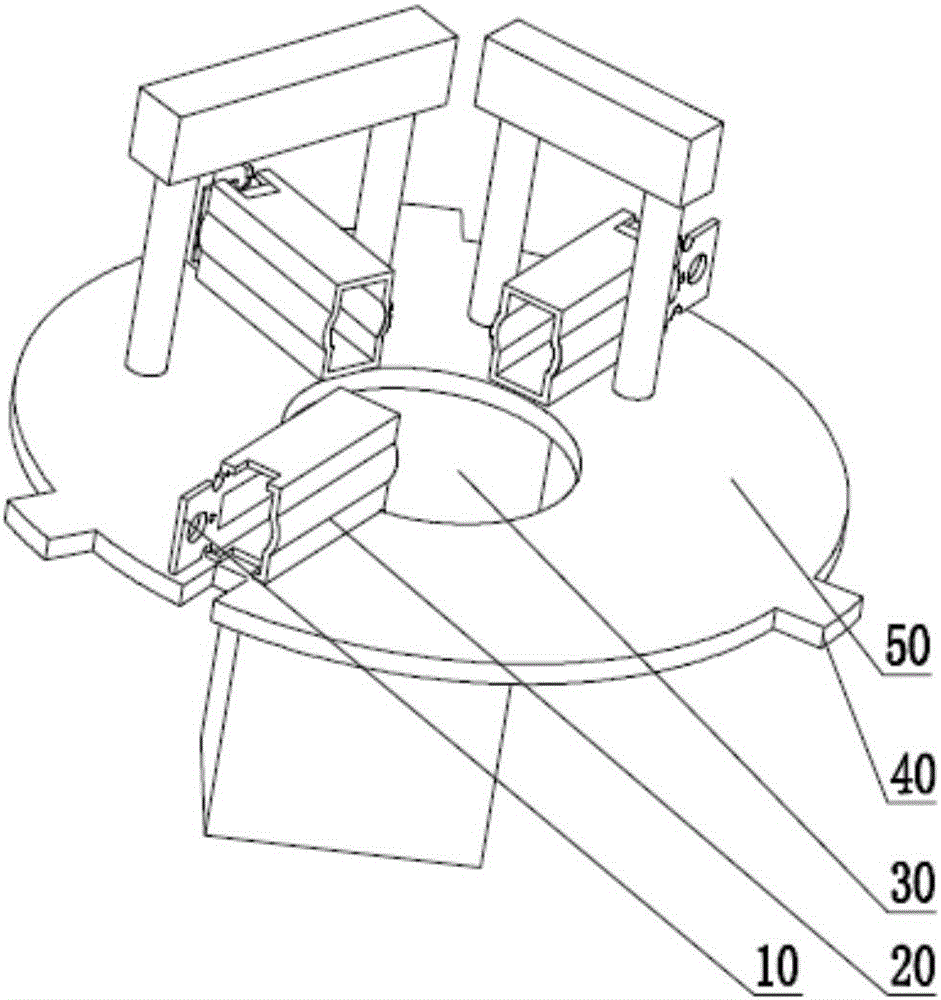
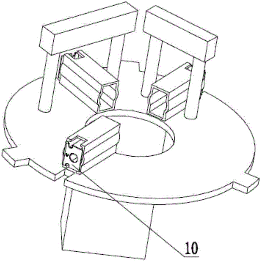
[0002] in the attached figure 1 During the processing of the parts shown, the flanging 10 needs to be bent, so as to realize the figure 2 However, due to the structural characteristics of the parts, especially the position of the flange, there is a lack of processing equipment that can automatically bend the flange of the parts accurately. The existing technology is mainly done manually. Bending, while manual operation can only bend different flanges separately, so a part has to be bent three times before it can be formed, which is labor-intensive and the processing efficiency is low
[0003] At the same time, due to the non-standard manual bending operation, the turning angle of each flange is often not uniform. In addition, due to manual operation, the flange may be deformed and damaged, which makes it difficult to effectively guarantee the quality of parts.

Method used


Image

  • Automatic bending mechanism and method for angle of brush box
  • Automatic bending mechanism and method for angle of brush box
  • Automatic bending mechanism and method for angle of brush box

Examples


Embodiment Construction

[0034] Objects, advantages and features of the present invention will be illustrated and explained by the following non-limiting description of preferred embodiments. These embodiments are only typical examples of applying the technical solutions of the present invention, and all technical solutions formed by adopting equivalent replacements or equivalent transformations fall within the protection scope of the present invention.

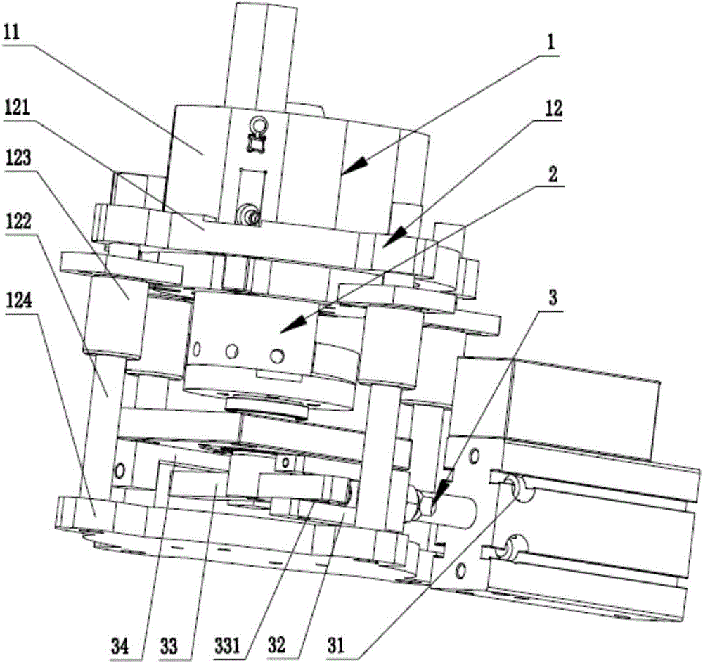
[0035] The brush box angle automatic bending mechanism disclosed by the present invention, as attached image 3 shown, including

[0036] The product-to-be-processed fixing carrier 1 is used to fix the product to be processed;

[0037] The rotary bending mechanism 2 is used to bend the flange 10 of the product to be processed on the product carrier 1, and the rotary bending mechanism 2 is arranged coaxially with the fixed carrier 1 of the product to be processed;

[0038] The driving mechanism 3 is used to drive the rotary bending mechanism 2 to re...


PUM


Abstract

The invention discloses an automatic bending mechanism and method for the angle of a brush box. The automatic bending mechanism comprises a fixing carrier for a product to be machined, a rotating bending mechanism and a driving mechanism, wherein the fixing carrier for a product to be machined is used for fixing a product to be machined, the rotating bending mechanism is used for bending flanges of the product to be machined on the fixing carrier for a product to be machined, the rotating bending mechanism and the fixing carrier for a product to be machined are coaxially arranged, and the driving mechanism is used for driving the rotating bending mechanism to rotate in the horizontal direction in a reciprocating mode. The automatic bending mechanism is elaborate in design and simple in structure, the product is positioned through the fixing carrier for a product to be machined, then three arc bending push heads on the rotating bending mechanism are made to apply push force to the flanges respectively through the rotating movement, the three flanges on the product to be machined are synchronously and precisely bent, the whole bending process is automatically carried out, efficiency is high, and the influence of manual operation is avoided; thus, the problems of nonuniformity of bending angles in manual operation, deformation and breakage of the flanges and the like are solved, and the machining quality of the end product is ensured.

Description

technical field [0001] The invention relates to bending equipment and a processing method thereof, in particular to a brush box angle automatic bending mechanism and method. Background technique [0002] in the attached figure 1 During the processing of the parts shown, the flanging 10 needs to be bent, so as to realize the figure 2 However, due to the structural characteristics of the parts, especially the position of the flange, there is a lack of processing equipment that can automatically bend the flange of the parts accurately. The existing technology is mainly done manually. Bending, while manual operation can only bend different flanges separately, so a part has to be bent three times before it can be formed, which is labor-intensive and the processing efficiency is low. [0003] At the same time, due to the non-standard manual bending operation, the turning angle of each flange is often not uniform. In addition, due to manual operation, the flange may be deformed ...

Claims


Application Information

Patent Timeline
IPC IPC(8): B65B47/04
CPCB65B47/04
Inventor 王越
Owner 昆山新井田智能设备有限公司
Why Eureka
Eureka Blog
Learn More