Meat cutter

The technology of a meat slicer and rack is applied in the direction of processed meat, meat processing equipment, metal processing, etc. It can solve the problems of troublesome cleaning, difficult cleaning, and continuous cutting of meat, so as to ensure the effect of meat cutting, simple cleaning and clean effect

Inactive Publication Date: 2017-01-04
ZHUHAI EAGLE MECHANICAL & ELECTRICAL CO LTD
View PDF12 Cites 3 Cited by
  • Summary
  • Abstract
  • Description
  • Claims
  • Application Information

AI Technical Summary

Problems solved by technology

[0003] The problems existing in the existing meat slicer are: firstly, the cutter bar of the meat slicer cannot be disassembled, which causes troublesome cleaning and is difficult to clean, so that odor is generated, which affects the use; secondly, after the blades on the cutter set are worn, There are easy gaps between the two matching blades, resulting in poor cutting effect and problems such as cutting meat

Method used


Image

  • Meat cutter
  • Meat cutter
  • Meat cutter

Examples


Embodiment Construction

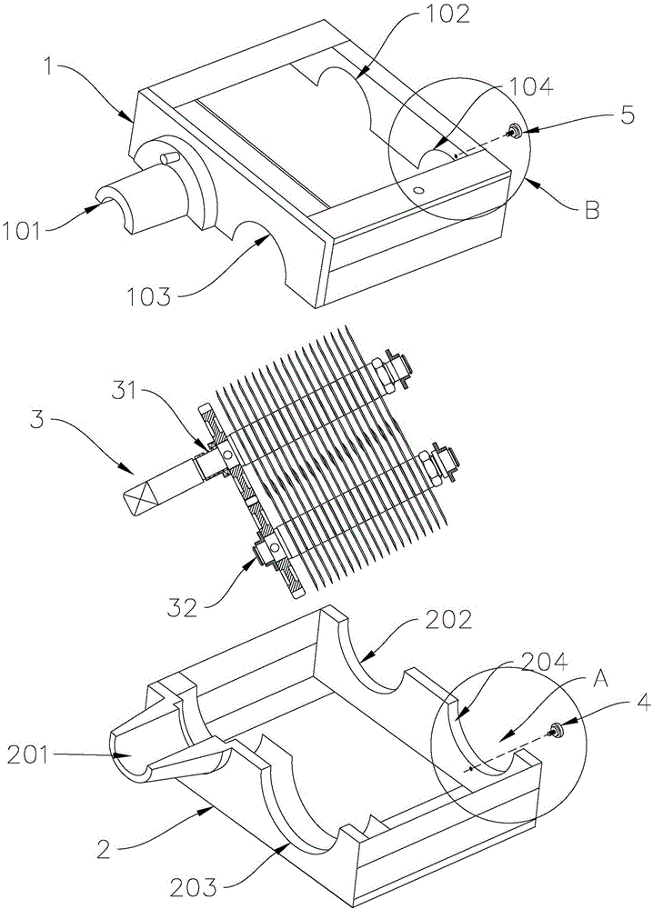
[0026] The meat cutting machine of the present invention includes a frame and a cutter group installed in the frame, and a cutting edge area is formed between two blades on the cutter group so that the meat piece entering from the feed port is cut into pieces by the cutter group. Strip or sheet, and then sent out from the outlet of the rack.

[0027] see figure 1 , figure 1 It is an exploded view of the structure of the meat slicer. The frame includes an upper frame 1 and a lower frame 2, and the upper frame 1 and the lower frame 2 are jointly combined into a frame for positioning the cutter group 3. The upper frame 1 is similar in structure to the lower frame 2. The upper frame 1 is an open cover with connecting walls all around. Mounting positions are arranged on both side walls of the upper frame 1. The mounting positions on the upper frame 1 include The input shaft limiting part 101 , the driving shaft limiting part 102 , the driven shaft first limiting part 103 and the...


PUM


Abstract

The invention provides a meat cutter. The meat cutter comprises a machine frame and a cutter set, wherein the cutter set comprises at least two sets of cutter rods, and blades on every two adjacent sets of cutter rods are arranged in a staggered mode to form a cutting edge area; the machine frame comprises an upper machine frame body and a lower machine frame body which are detachably connected, and the cutter rods are supported by the lower machine frame body in a rotary mode and located on the upper machine frame body in a limited mode. The meat cutter further comprises an adjusting top rod, at least one threaded through hole is formed in the side wall of the machine frame, and the adjusting top rod is in screw-thread fit with the threaded through holes. Each cutting rod comprises a shaft shoulder, and the adjusting top rod penetrates through the threaded through holes to abut against the end face of the shaft shoulder. Due to the fact that the upper machine body and the lower machine frame body are detachably connected and the cutter rods can be dismounted and taken out conveniently, the cutter rods can be easily and thoroughly cleaned. By adjusting the adjusting top rod installed on the side wall of the machine frame, the distance between the blades which act on one another can be adjusted, close fit between every two matched blades is guaranteed, and the meat cutting effect of the meat cutter is guaranteed.

Description

technical field [0001] The invention relates to the field of food processing equipment, in particular to a meat cutter. Background technique [0002] Existing meat slicer adopts the principle of cutting edge region similar to scissors to realize the cutting process of meat. Two cutter bars are arranged in the frame of the meat slicer, and the relative rotation between the two cutter bars, and the two The blades on the root cutter bar are interlaced to form a cutting edge area, and multiple blades installed side by side on the same cutter bar can realize batch cutting of meat products, and have very high cutting efficiency. [0003] The problems existing in the existing meat slicer are: firstly, the cutter bar of the meat slicer cannot be disassembled, which causes troublesome cleaning and is difficult to clean, so that odor is generated, which affects the use; secondly, after the blades on the cutter set are worn, A gap is likely to appear between the two matching blades, r...

Claims


Application Information

Patent Timeline
Patent Type & Authority Applications(China)
IPC IPC(8): B26D1/24B26D5/08B26D7/26
CPCB26D1/24B26D5/08B26D7/2621B26D7/2635B26D2210/02A22C17/0033A22C17/0013
Inventor 周忠德杨师亮
Owner ZHUHAI EAGLE MECHANICAL & ELECTRICAL CO LTD
Why Eureka
Try Eureka