
Wearable lower extremity exoskeleton power-assisted robot

An exoskeleton and robot technology, applied in the field of wearable lower extremity exoskeleton assisting robots, can solve the problems of performance degradation, complexity, and many hydraulic cylinders, and achieve the effects of reducing constraints, simplifying design, and increasing comfort

Inactive Publication Date: 2017-01-04
SOUTHWEST JIAOTONG UNIV
View PDF11 Cites 17 Cited by
  • Summary
  • Abstract
  • Description
  • Claims
  • Application Information

AI Technical Summary

Problems solved by technology

[0002] The existing products are part of the lower extremity exoskeleton robot with electric control, which cannot meet the requirements of large load, the control part is relatively complicated, and the performance in harsh environments has declined
Some hydraulically controlled hydraulic lower extremity exoskeletons also have problems such as too many hydraulic cylinders and complicated oil circuit control; there is a problem that the length of the thigh and calf cannot be adjusted, and even if it is adjustable, the operation is very complicated; the hip joint lacks the freedom to move freely The existence of these problems has seriously affected the human-machine comfort of exoskeleton robots

Method used


Image

  • Wearable lower extremity exoskeleton power-assisted robot
  • Wearable lower extremity exoskeleton power-assisted robot
  • Wearable lower extremity exoskeleton power-assisted robot

Examples


Embodiment Construction

[0026] The present invention will be further described below in conjunction with the accompanying drawings, but the protection scope of the present invention is not limited to the following description.

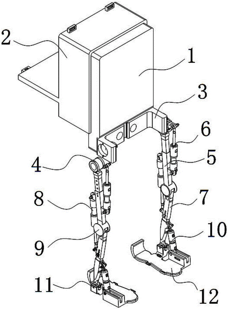
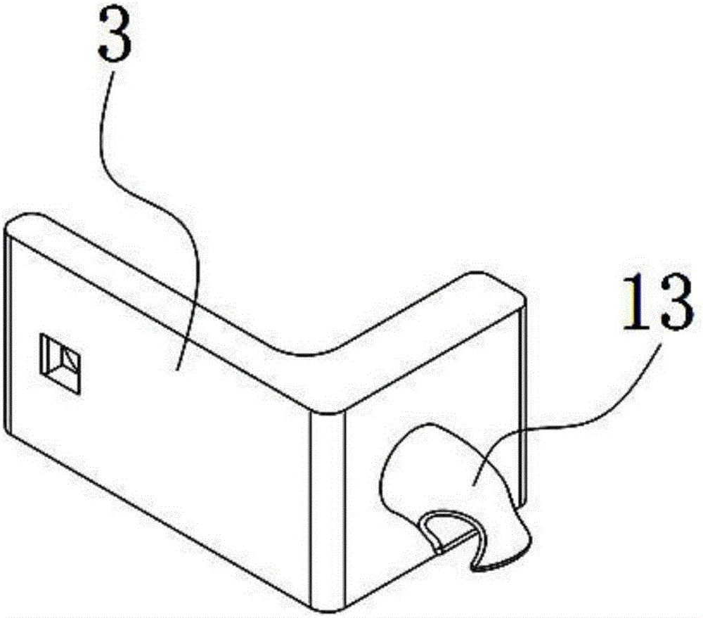
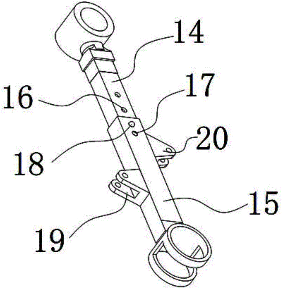
[0027] like figure 1 As shown, a wearable lower extremity exoskeleton power-assisted robot includes a back frame 1, a hip joint 4, a thigh assembly 5, a calf assembly 7, a knee joint sleeve 9, an ankle joint 11 and a shoe sole 12, and the front side of the back frame 1 is arranged symmetrically There are hip joint guards 3, hip joints 4 are installed on both sides of each hip joint guard 3, the upper end of the thigh assembly 5 is connected to the hip joint 4, and the lower end is connected to the upper end of the lower leg assembly 7 through the knee joint sleeve 9 , the lower end of the calf assembly 7 is connected to the ankle joint 11, the ankle joint 11 is fixed on the outside of the sole 12, a hip joint hydraulic cylinder 6 is installed between the hip joint 4 and the f...


PUM


Abstract

The invention discloses a wearable lower extremity exoskeleton power-assisted robot. The wearable lower extremity exoskeleton power-assisted robot comprises a back frame, hip joints, thigh assemblies, calf assemblies, knee joint sleeves, ankle joints and shoe soles. The front side of the back frame is provided with hip joint protective plates. The hip joints are installed on the two sides of each hip joint protective plate. The upper ends of the thigh assemblies are connected with the hip joints, and the lower ends of the thigh assemblies are connected with the upper ends of the calf assemblies. The lower ends of the calf assemblies are connected with the ankle joints. The ankle joints are fixed to the outer sides of the shoe soles. A hip joint hydraulic oil cylinder is installed between each hip joint and the front side of the corresponding thigh assembly. A knee joint hydraulic oil cylinder is installed between the rear side of each thigh assembly and the rear side of the corresponding calf assembly. A foot hydraulic oil cylinder is installed between the front side of each calf assembly and the corresponding shoe sole. The hip joint hydraulic oil cylinders, the knee hydraulic oil cylinders and the foot hydraulic oil cylinders are controlled to stretch out and draw back by a hydraulic control system. The wearable lower extremity exoskeleton power-assisted robot has the advantages that large loads can be achieved, and automation can be achieved by controlling oil lines; and the size of all the components of the robot is adjustable, constraint to the hip joints is reduced after a soldier wears the robot, and the robot meet the principle of man-machine engineering better.

Description

technical field [0001] The invention relates to the technical field of power-assisted robots, in particular to a wearable lower limb exoskeleton power-assisted robot. Background technique [0002] Some of the existing products are lower limb exoskeleton robots controlled by electric motors, which cannot meet the requirements of large loads. The control part is relatively complicated, and the performance in harsh environments has declined. Some hydraulically controlled hydraulic lower extremity exoskeletons also have problems such as too many hydraulic cylinders and complicated oil circuit control; there is a problem that the length of the thigh and calf cannot be adjusted, and even if it is adjustable, the operation is very complicated; the hip joint lacks the freedom to move freely The existence of these problems has seriously affected the human-machine comfort of exoskeleton robots. Contents of the invention [0003] The purpose of the present invention is to overcome t...

Claims


Application Information

Patent Timeline
IPC IPC(8): B25J9/00
CPCB25J9/0006
Inventor 李敏杜彬张力峰谷敏周建容
Owner SOUTHWEST JIAOTONG UNIV
Learn More