Working method of automatic clamping device for large plate

A technology of clamping device and working method, which is applied in the field of plate processing, can solve problems such as potential safety hazards, high labor intensity, and unstable quality, and achieve the effects of improving efficiency, improving quality, and avoiding potential safety hazards

Active Publication Date: 2018-05-11
CHONGQING TIEMA IND GRP
View PDF6 Cites 0 Cited by
  • Summary
  • Abstract
  • Description
  • Claims
  • Application Information

AI Technical Summary

Problems solved by technology

[0003] The purpose of the present invention is to provide a working method of a large plate automatic clamping device to solve the problems of high labor intensity, low efficiency, unstable quality and potential safety hazards in the existing manual clamping and loosening plate processing methods The problem

Method used


Image

  • Working method of automatic clamping device for large plate
  • Working method of automatic clamping device for large plate

Examples


Embodiment 1

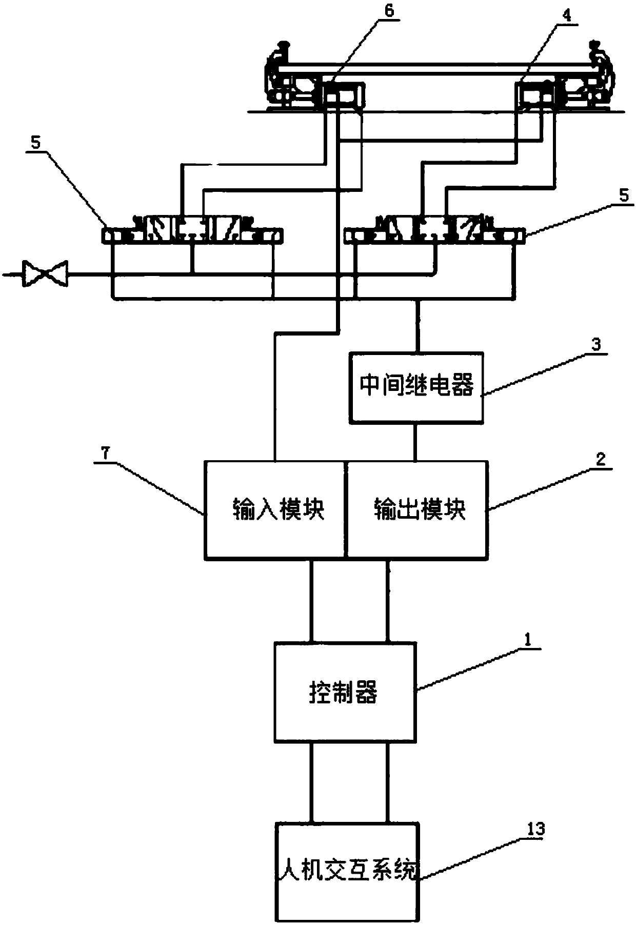
[0029] Such as figure 1 and figure 2 As shown, the large plate automatic clamping device includes a controller 1 and multiple clamping mechanisms; the signal output terminal of the controller 1 is electrically connected to the output module 2, and the signal output terminal of the output module 2 is connected with the signal of each clamping mechanism respectively. The input end is electrically connected; the clamping mechanism includes an intermediate relay 3 and two locking structures for locking the plate; the locking structure is connected with a cylinder 4 that controls its work; the cylinder 4 is connected with an electromagnetic reversing valve that controls its work 5. The two electromagnetic reversing valves 5 are electrically connected to the intermediate relay 3; the signal output terminal of the output module 2 is electrically connected to the signal input end of the intermediate relay 3; the electromagnetic reversing valve 5 is connected to an air source; the con...

Embodiment 2

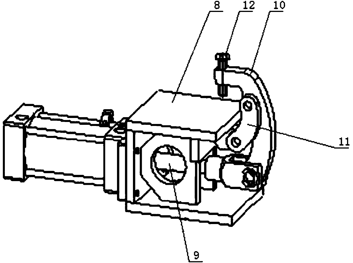
[0033] Such as figure 1 As shown, the difference between this embodiment and Embodiment 1 is that the clamping mechanism also includes two signal switches 6 for monitoring the action of the cylinder 4; the signal input end of the controller 1 is electrically connected with an input module 7, and the input module 7 The signal input end of each signal switch 6 is electrically connected with the signal output end of each signal switch 6; the cylinder 4 is monitored by the signal switch 6, and the cutter and the indenter 12 are placed to collide, causing damage to the cutter and the indenter 12.

[0034] The working method of the large plate automatic clamping device comprises the following steps:

[0035] 1.1 Place the locking structure according to the shape of the plate and fix it on the workbench; move the tool to the top of the indenter, input and store the current coordinate value of the indenter in the controller through the human-computer interaction system, and set thres...


PUM


Abstract

The invention discloses an automatic clamping device for large plates and a working method of the automatic clamping device. The problems that for an existing processing method for artificially clamping and loosening plates, the labor intensity is high, the efficiency is low, the quality is unstable, and potential safety hazards exist are mainly solved. The automatic clamping device for the large plates comprises a controller and multiple clamping mechanisms; an output module is electrically connected to the signal output end of the controller, and the signal output end of the output module is electrically connected to signal input ends of all clamping mechanisms separately; each clamping mechanism comprises an intermediate relay and two locking structures used for locking the plates; a cylinder which controls the corresponding locking structure to work is connected to each locking structure; a magnetic exchange valve which controls the corresponding cylinder to work is connected to each cylinder, and every two magnetic exchange valves are electrically connected with the corresponding intermediate relay; the signal output end of the output module is electrically connected with the signal input ends of the intermediate relays. In this way, according to the automatic clamping device for the large plates and the working method of the automatic clamping device, automatic collision avoidance of a pressure head to a tool is achieved, the purpose of automatically locking the plates is achieved, and very high practical value and popularization value are achieved.

Description

technical field [0001] The invention relates to the field of plate processing, in particular to an automatic clamping device for a large plate. Background technique [0002] At present, when processing large armor plates in the same industry, the plate is clamped and released manually before and after processing, and in the process of processing the periphery of the large plate, in order to avoid the tool walking track and the tool from interfering with several pressure plates , the operator needs to repeatedly loosen and clamp the pressing plate; the existing manual clamping and unclamping plate processing methods have the problems of high labor intensity, low efficiency, unstable quality, and potential safety hazards. Contents of the invention [0003] The purpose of the present invention is to provide a working method of a large plate automatic clamping device to solve the problems of high labor intensity, low efficiency, unstable quality and potential safety hazards in...

Claims


Application Information

Patent Timeline
Patent Type & Authority Patents(China)
IPC IPC(8): B23Q3/08B23Q17/22
CPCB23Q3/08B23Q17/2208B23Q2703/04
Inventor 朱成刚韩世伟蒋晓吴旭仲琳
Owner CHONGQING TIEMA IND GRP
Why Eureka
Try Eureka