
Convenient-to-operate multifunctional punching and shearing machine with high shearing quality and punching and shearing method thereof

An easy-to-operate, punching and shearing machine technology, applied in other manufacturing equipment/tools, metal processing equipment, feeding devices, etc., to achieve the effect of high shearing quality, easy operation, and improved shearing accuracy

Active Publication Date: 2017-01-04
ANHUI ZHONGYI MACHINE TOOL MFG
View PDF11 Cites 0 Cited by
  • Summary
  • Abstract
  • Description
  • Claims
  • Application Information

AI Technical Summary

Problems solved by technology

[0014] The purpose of the present invention is to solve the problems that the above-mentioned punching and shearing machine exists, and provide a multifunctional punching and shearing machine and a punching and shearing method with high cutting quality and easy operation; the present invention solves the multiple defects of the existing punching and shearing machine, The use effect of the punching and shearing machine is improved, and the transformation cost of the existing punching and shearing machine is low, and the economic benefit is good

Method used


Image

  • Convenient-to-operate multifunctional punching and shearing machine with high shearing quality and punching and shearing method thereof
  • Convenient-to-operate multifunctional punching and shearing machine with high shearing quality and punching and shearing method thereof
  • Convenient-to-operate multifunctional punching and shearing machine with high shearing quality and punching and shearing method thereof

Examples


Embodiment 1

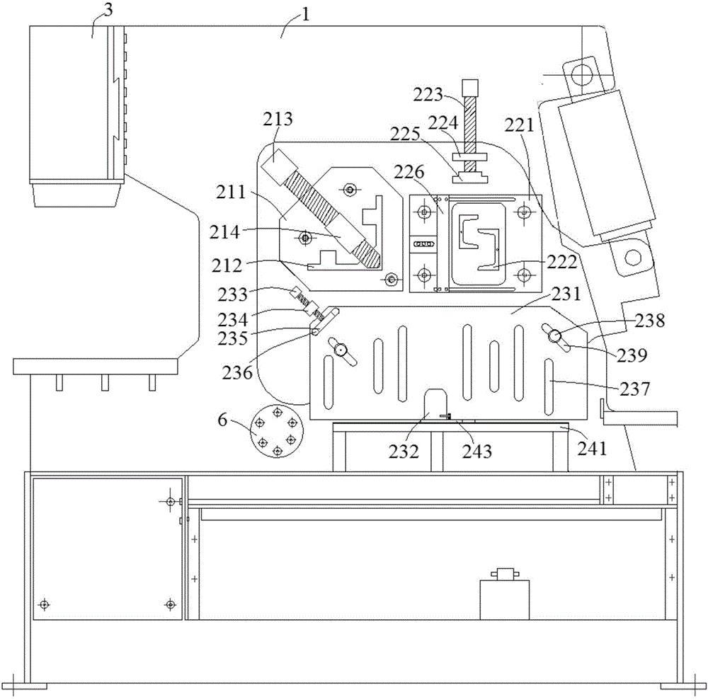
[0060] Combine figure 1 In this embodiment, a multifunctional punching and shearing machine with high cutting quality and convenient operation is provided with a pressing mechanism on the front of the punching and shearing machine body 1. The pressing mechanism includes three-station pressing materials. Components; where:

[0061] The first material pressing assembly includes a first material limiting plate 211, a first pressing screw 213, and a first fixing sleeve 214. The first material limiting plate 211 is fixed to the fuselage 1 by bolts. The first material limiting plate 211 is provided with There is a first feeding trough 212, and the first feeding trough 212 has an irregular "L"-shaped structure. The first pressing screw 213 is arranged on the first material limiting plate 211 through the first fixing sleeve 214, and the first pressing screw 213 can move toward the top angle of the first feeding trough 212. The first pressing component of this embodiment is mainly suitab...

Embodiment 2

[0069] See Image 6 In this embodiment, a multifunctional punching and shearing machine with high cutting quality and convenient operation includes a lower mold base pressing mechanism. The inventor pointed out that Figure 5 It is a schematic diagram of the structure of a double-station punching and shearing machine previously applied by the inventor. Considering the structure design of the existing punching and shearing machine, the working table 423 is designed to be relatively short, and the lower mold base 421 is installed on the working table 423. On the upper, the lower mold base 421 is generally designed with two mold holes 422. When changing the work position, the lower mold base 421 needs to be removed, turned around and then installed on the workbench 423. When cutting profiles of different shapes , It is necessary to replace different punching and shearing molds, so a lot of working time is spent on mold removal and mold assembly, labor efficiency is low, and it is v...

Embodiment 3

[0074] See Figure 7 with Figure 8 In this embodiment, a multifunctional punching and shearing machine with high cutting quality and convenient operation includes a blade matching mechanism. The core of the blade matching mechanism is a blade matching eccentric shaft 6. The blade matching eccentric shaft 6 6 An external fixing plate 61, a first concentric section 63, a second eccentric section 64 and a third concentric section 65 are arranged in sequence. The knife plate matches the eccentric shaft 6 across the fuselage 1, and the external fixing plate 61 is provided with a fixing plate screw hole 62 , The outer fixing plate 61 is fixed with the wall plate of the fuselage 1 through bolts inserted into the screw holes 62 of the fixing plate. The knife plate of this embodiment matches the eccentric shaft 6. As the name implies, the external fixing plate 61, the first concentric section 63 and the third concentric section 65 are concentric, and the second eccentric section 64 is n...


PUM


Abstract

The invention discloses a convenient-to-operate multifunctional punching and shearing machine with high shearing quality and a punching and shearing method thereof, and belongs to the technical field of machining equipment. The multifunctional punching and shearing machine provided by the invention comprises a knife board matching mechanism, wherein the knife board matching mechanism comprises a knife board matching eccentric shaft, wherein the knife board matching eccentric shaft is provided with an outer fixing plate, a first concentric section, a second eccentric section and a third concentric section sequentially; the knife board matching eccentric shaft transversely penetrates a machine body and is fixed to a wallboard of the machine body through the outer fixing plate; and knife boards are connected with the second eccentric section of the knife board matching eccentric shaft through a connecting plate. The multifunctional punching and shearing machine enables the knife board of a moveable knife to rotate around an elliptic radian and the rotation by the method can guarantee that the knife board of the moveable knife and a knife board of a static knife achieve position matching, so that a knife edge of the moveable knife and a knife edge of the static knife can be matched; the method is implemented once for all, that is, mismatching is not liable to occur when blades are changed again after one-time adjustment, so the use of customers is greatly facilitated.

Description

Technical field [0001] The invention relates to the technical field of mechanical processing equipment, and more specifically, to a multifunctional punching and shearing machine with high cutting quality and convenient operation and a punching and shearing method thereof. Background technique [0002] The punching and shearing machines currently in use mainly include flywheel punching and shearing machines and hydraulic combined punching and shearing machines, and their functions have gradually developed from a single punching, shearing or bending function to a multi-function. Among them, hydraulic combined punching and shearing machines generally have five stations: standard configuration punching station, angle steel cutting station, bar cutting station, plate shearing station, corner cutting station, etc., which can realize multiple Various section steels and plates are processed to achieve the effect of one machine with multiple functions. [0003] However, although the functi...

Claims


Application Information

Patent Timeline
Patent Type & Authority Applications(China)
IPC IPC(8): B23P23/04B21D43/00B21D28/24B21D43/28
CPCB21D28/24B21D43/003B21D43/28B23P23/04
Inventor 叶元义叶良鹏臧文富
Owner ANHUI ZHONGYI MACHINE TOOL MFG
Learn More