
metal forming equipment

A metal forming and equipment technology, which is applied in the field of amorphous alloy smelting and die-casting equipment, can solve the problems of damage to molds, mold defects, and defects of air holes in molded parts, and achieve the effects of compact equipment structure, guaranteed yield, and high vacuum degree

Active Publication Date: 2018-11-27
宁波保税区海天智胜金属成型设备有限公司
View PDF10 Cites 0 Cited by
  • Summary
  • Abstract
  • Description
  • Claims
  • Application Information

AI Technical Summary

Problems solved by technology

Due to structural limitations, the vertical die-casting machine has relatively high requirements for the height of the factory building, and it is easy to splash the molten liquid on the surface of the mold during the pouring process, causing mold defects and damaging the mold
For horizontal die-casting machines, in order to maintain a vacuum environment, one method is to fill the inside of the sealed vacuum chamber with protective gas to prevent the oxidation of metal during smelting and molding, but there may be porosity defects in the molded parts
The other is to evacuate the closed vacuum chamber to keep the amorphous solution in a vacuum environment during the entire molding process, but the existing equipment cannot well maintain the vacuum required for the amorphous alloy molded product in the vacuum chamber, resulting in The yield of amorphous products is still not high

Method used


Image

  • metal forming equipment
  • metal forming equipment
  • metal forming equipment

Examples


Embodiment Construction

[0039] Preferred embodiments of the present invention will be described in detail below with reference to the accompanying drawings, so as to better understand the purpose, features and advantages of the present invention. It should be understood that the embodiments shown in the drawings are not intended to limit the scope of the present invention, but only to illustrate the essence of the technical solutions of the present invention.

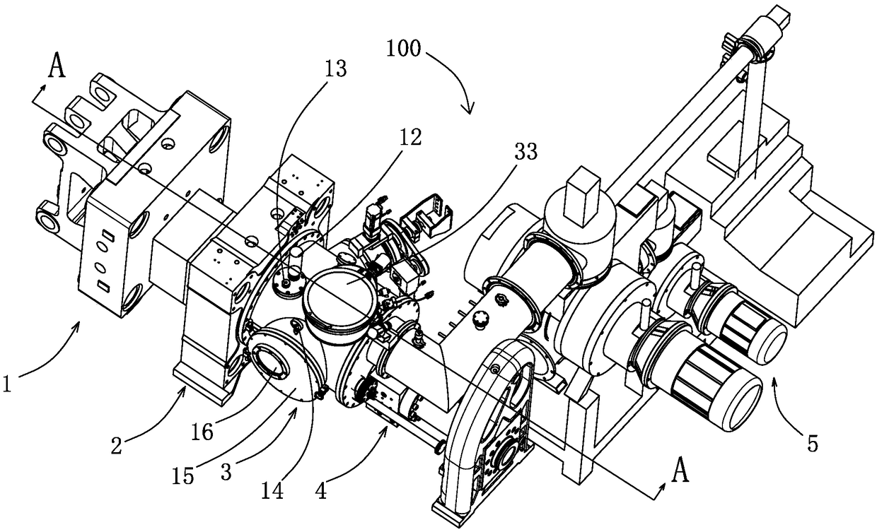
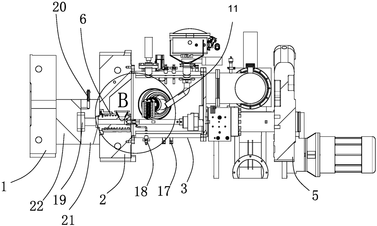
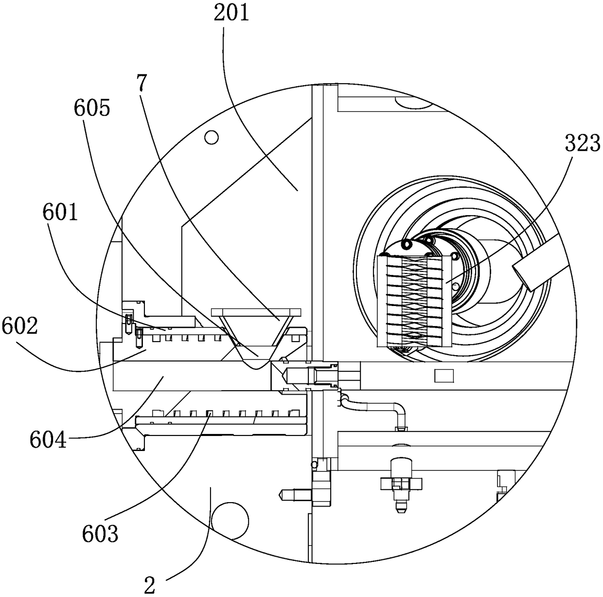
[0040] Such as figure 1 As shown, the amorphous alloy is smelted and die-casted, and the metal forming equipment 100 includes a moving template 1 , a fixed template 2 , a melting furnace 3 , an injection device 4 and a vacuum device 5 . The fixed mold 21 and the movable mold 22 of the mold are installed on the fixed template 1 and the movable template 2 respectively, which can complete the opening and closing actions. When the fixed mold and the movable mold are closed, a mold cavity 19 is defined between them. The cavity vacuuming device 20 ...


PUM


Abstract

The invention discloses a metal forming equipment. The metal forming equipment includes a movable template, a fixed template, an injection cylinder and a melting furnace, wherein the movable mold and the fixed mold of the mold are installed on the movable template and the fixed template respectively, and a gap is defined between the movable mold and the fixed mold when they are closed. cavity. The smelting furnace is provided with a feeding port, a closed chamber and a melting device. The melting device has a melting vessel capable of heating and melting the material from the feeding port into a melt. The injection barrel is installed in the fixed template and has a melt inlet. A concave cavity is provided on the side of the fixed formwork facing the melting furnace, and the concave cavity communicates with the closed chamber and the melt inlet at the same time, and the melt inlet is located in the concave cavity. The melting container can be moved between two positions, wherein in the first position, the melting container can receive the material to be melted, and in the second position, the melt formed by melting the material in the melting container can be transferred to the melt inlet. The metal forming equipment of the present invention can achieve a high yield.

Description

technical field [0001] The invention relates to an amorphous alloy die-casting molding technology, in particular to amorphous alloy melting die-casting molding equipment in a vacuum environment. Background technique [0002] The amorphous alloy material is solidified by ultra-rapid cooling. When the alloy is solidified, the atoms have no time to arrange and crystallize in an orderly manner. The obtained solid alloy has a long-range disordered structure, and there are no grains and grain boundaries of the crystalline alloy. [0003] Conventional metal solution, when molding components in die-casting molding equipment, hard spots formed by oxidized slag inclusions are likely to appear during smelting and molding, and because the metal solution fills the mold cavity in a high-speed jet state, the gas in the cavity cannot be discharged in time , will inevitably be involved in the metal solution, and remain in the die-casting part in the form of pores, resulting in pore defects i...

Claims


Application Information

Patent Timeline
Patent Type & Authority Patents(China)
IPC IPC(8): B22D17/14C22C1/00
CPCB22D17/14C22C1/11
Inventor 葛琪威陈列牟小龙张旭民吴雷斌徐雷叶盛
Owner 宁波保税区海天智胜金属成型设备有限公司
Learn More