Hole-crimped forming die

A technology of forming molds and forming concave molds, which is applied in the directions of forming tools, manufacturing tools, feeding devices, etc., can solve the problems of inability to monitor the flow direction of the material of the workpiece, affecting the processing quality of the workpiece, and inconsistency in the height of the turning hole. Design and implementation, simple structure, ensure the effect of processing quality

Inactive Publication Date: 2017-01-04
GREAT WALL MOTOR CO LTD
View PDF10 Cites 2 Cited by
  • Summary
  • Abstract
  • Description
  • Claims
  • Application Information

AI Technical Summary

Problems solved by technology

In the existing technology, the mold used for forming the hole-turning structure of the workpiece such as the coil spring support can only be positioned by the shape of the workpiece during processing, and the flow direction of the workpiece material cannot be monitored during the molding process, so it is easy to As a result, the centerline of the hole to be machined on the part deviates from the centerline of the hole-turning punch on the mold, which in turn will cause inconsistency in the hole-turning height and affect the processing quality of the part

Method used


Image

  • Hole-crimped forming die
  • Hole-crimped forming die
  • Hole-crimped forming die

Examples


Embodiment Construction

[0029] It should be noted that, in the case of no conflict, the embodiments of the present invention and the features in the embodiments can be combined with each other.

[0030] The present invention will be described in detail below with reference to the accompanying drawings and examples.

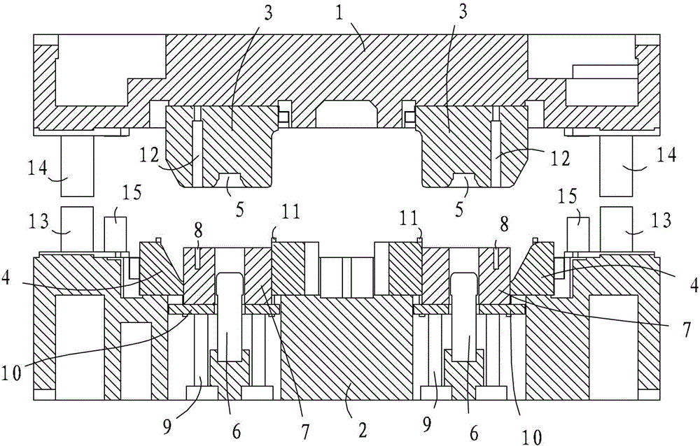
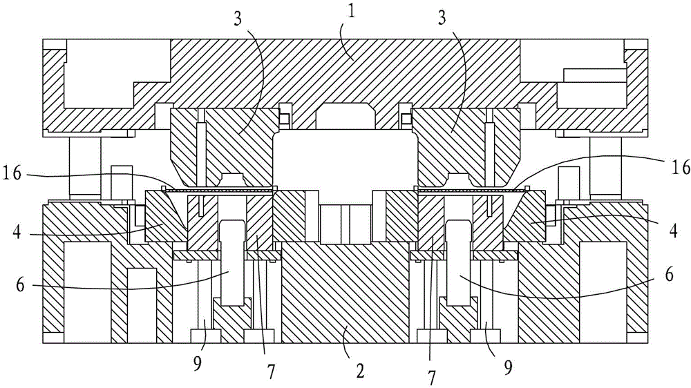
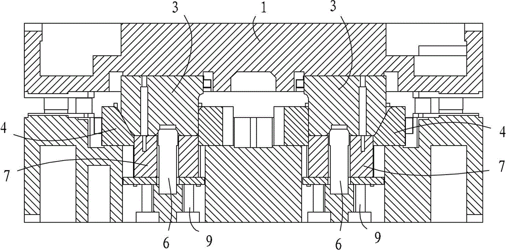
[0031] This embodiment relates to a hole-turning forming mold, which is used for forming and processing the hole-turning structure of workpieces such as coil spring supports, such as figure 1 As shown in , the hole-turning forming mold includes a lower mold base 2 with a forming die 4, and an upper die base 1 with a forming punch 3, and a hole-turning punch 6 is also provided in the forming die 4, corresponding to the hole-turning punch 6. On the forming punch 3, there is a punching die 5. In the forming die 4 , a supporting part that can support the workpiece placed in the forming die 4 is also movable, and the supporting part is arranged on the peripheral side of the hole-turning punc...


PUM


Abstract

The invention provides a hole-crimped forming die used for forming hole-crimped structures on workpieces. The hole-crimped forming die comprises a lower die holder with a female forming die body, and an upper die holder with a male forming die body. A male hole-crimping die body is further arranged in the female forming die body, and a female hole-crimping die body corresponding to the male hole-crimping die body is arranged on the male forming die body. Supporting parts used for supporting a workpiece arranged in the female forming die body are movably arranged on the peripheral side of the male hole-crimping die body in the female forming die body. The hole-crimped forming die further comprises a driving device which is arranged between the supporting parts and the lower die holder and used for conducting driving supporting on the supporting parts. When the upper die holder and the lower die holder are closed, the supporting parts are in abutting fit with the male forming die body via the workpiece and follow the male forming die body. When the upper die holder and the lower die holder are opened, the supporting parts are driven by the driving device to move along the central line of the male hole-crimping die body. According to the hole-crimped forming die, the central line of a to-be-machined hole of the workpiece can be kept in coincidence with the central line of the male hole-crimping die body of the forming die during machining, and the machining quality of a hole-crimped structure of the workpiece is guaranteed.

Description

technical field [0001] The invention relates to the technical field of moulds, in particular to a hole turning forming mould. Background technique [0002] Trailing arm torsion beam semi-independent suspension is a suspension structure specially designed for rear wheels. The shock absorber and coil spring act as a soft connection, and the hydraulic shock absorber and coil spring play the role of shock absorption and supporting the vehicle body. In the actual structure, the helical spring is supported by the helical spring support, which includes the helical spring support of the guide arm, the helical spring support of the torsion beam, and the helical spring support of the shock absorber. [0003] At present, the processing technology of the coil spring support generally includes drop punching, forming and turning holes, and punching small holes. Among them, the center hole of the coil spring support is an important structure, and in the subsequent welding process, this h...

Claims


Application Information

Patent Timeline
Patent Type & Authority Applications(China)
IPC IPC(8): B21D37/10B21D43/00B21D53/88
Inventor 周永丽刘建国陈龙华柴龙何清刘朋朋杨向东王越
Owner GREAT WALL MOTOR CO LTD
Why Eureka
Try Eureka