
Grid lining plate for ball mill

A ball mill and liner technology, applied in grain processing and other directions, can solve problems such as low work efficiency, inability to disassemble, bolt damage, etc., and achieve the effect of good effect, convenient disassembly and maintenance

Inactive Publication Date: 2017-01-04
芜湖银海机械制造有限公司
View PDF0 Cites 5 Cited by
  • Summary
  • Abstract
  • Description
  • Claims
  • Application Information

AI Technical Summary

Problems solved by technology

[0005] However, the severe impact of the grinding balls on the liner of the ball mill will cause the liner to wear and thin, causing problems such as non-wear resistance, easy breakage, and unsatisfactory dribbling effect, resulting in low work efficiency, low output, and virtually increased costs.
[0006] In particular, the existing ball mill grid liner is generally fixed on the cylinder by bolts, and there is a gap between the through hole of the fixing bolt and the bolt, and gravel, powder, etc. will enter in the gap and the bolt and gravel will be separated. Direct collision with the powder will easily damage and deform the bolts, which will make the subsequent disassembly and maintenance of the lattice lining more difficult and impossible to disassemble, which is very troublesome

Method used


Image

  • Grid lining plate for ball mill
  • Grid lining plate for ball mill
  • Grid lining plate for ball mill

Examples


Embodiment Construction

[0023] The technology of the present invention will be described in detail below in conjunction with the accompanying drawings and specific preferred embodiments, so that the advantages and characteristics of the technology of the present invention can be more easily understood by those skilled in the art. These embodiments are for illustrative purposes only and are not intended to The scope of the present invention is defined.

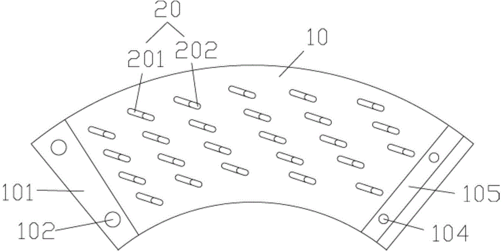
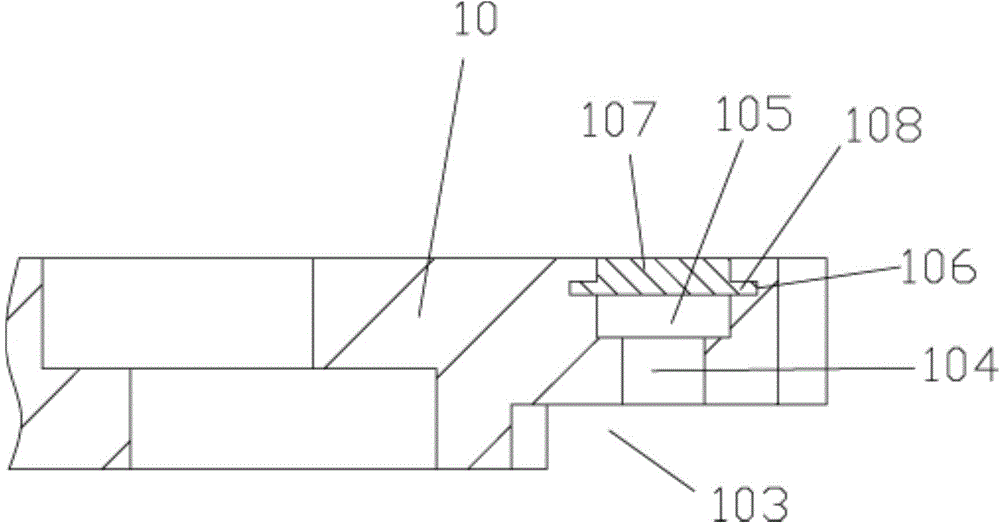
[0024] Examples, see e.g. Figure 1 to Figure 3 As shown, a grid liner for a ball mill includes a liner body 10, the middle of which liner body 10 has a plurality of ore discharge through holes 20, and the lower part of the left side wall of liner body 10 has an outwardly extending connection part 101, the connecting part 101 has a connecting through hole 102, the lower part of the right side wall surface of the liner body 10 has a groove 103 for the connection part 101 of the adjacent liner body 10 to insert, and the top surface of the groove 103 has...


PUM


Abstract

The invention discloses a grid lining plate for a ball mill. The grid lining plate comprises lining plate bodies. A plurality of ore discharging through holes are formed in the middle portion of each lining plate body. A connecting part extending outwards is arranged at the lower portion of the left side wall face of each lining plate body and provided with connecting through holes. A groove for the connecting part of the adjacent corresponding lining plate body to be inserted is formed in the lower portion of the right side wall face of each lining plate body. Through holes are formed in the top faces of the grooves. A microscler groove is formed in the upper portion of the right side of each lining plate body and communicates with the corresponding through hole. Inserting grooves are formed in the two side walls of each microscler groove. Microscler stop blocks are inserted in the microscler grooves in a sleeved manner. Protruding strips on the two sides of each microscler stop block are embedded in the corresponding inserting grooves. By means of the grid lining plate, gravel can be discharged out of the ore discharging through holes; and meanwhile, the microscler stop blocks are arranged to protect bolts against damage, subsequent dismounting and maintaining of the lining plate are convenient, and the effect of the grid lining plate is good.

Description

[0001] Technical field: [0002] The technology of the invention relates to the technical field of ball mill equipment, and more specifically relates to a grid liner for a ball mill. [0003] Background technique: [0004] Ball mill is a kind of grinding equipment widely used in the fields of electric power, ceramics, cement and mineral processing. Its basic working principle is: the cylinder of the ball mill rotates at a certain speed, and the grinding balls at the bottom of the cylinder of the ball mill are attached to the lining plate of the cylinder under the action of centrifugal force and friction. When the grinding ball is brought to a certain height, it is thrown down due to its own gravity, and the abrasive material at the bottom of the cylinder is impacted and crushed and ground. The liner of the ball mill is used to protect the cylinder from the direct impact and friction of the grinding body and the material. At the same time, different forms of liner can be used t...

Claims


Application Information

Patent Timeline
Patent Type & Authority Applications(China)
IPC IPC(8): B02C17/22
Inventor 冯航泽
Owner 芜湖银海机械制造有限公司
Learn More