High-precision, wide-range and large-work-distance auto-collimation device and method thereof

A high-precision, working distance technology, applied in the direction of measuring devices, optical devices, active optical measuring devices, etc., can solve the problems that the reflected beam deviates from the entrance pupil, the range cannot be too large, and the self-collimation and micro-angle measurement cannot be realized.

Active Publication Date: 2016-12-21
HARBIN INST OF TECH
View PDF8 Cites 6 Cited by
  • Summary
  • Abstract
  • Description
  • Claims
  • Application Information

AI Technical Summary

Problems solved by technology

[0008] First, the range of the angle between the normal of the mirror surface of the measured object 5 and the optical axis of the laser autocollimator should not be too large, otherwise the reflected beam will deviate from the entrance pupil of the laser autocollimator optical system, resulting in failure to achieve self-collimation Straight and micro angle measurement;
[0009] Second, the distance between the mirror surface of the measured object 5 and the entrance pupil of the laser autocollimator should not be too far away, otherwise as long as the reflected optical axis deviates from the optical axis of the autocollimator by a small angle, the reflected beam will deviate from the optical system of the laser autocollimator The entrance pupil, which leads to the inability to achieve self-collimation and micro-angle measurement
[0010] The above two problems limit the use of traditional autocollimation instruments to small angles and small working distances.

Method used


Image

  • High-precision, wide-range and large-work-distance auto-collimation device and method thereof
  • High-precision, wide-range and large-work-distance auto-collimation device and method thereof
  • High-precision, wide-range and large-work-distance auto-collimation device and method thereof

Examples


specific Embodiment 1

[0084] This embodiment is an embodiment of an autocollimation device with high precision, wide range and large working distance.

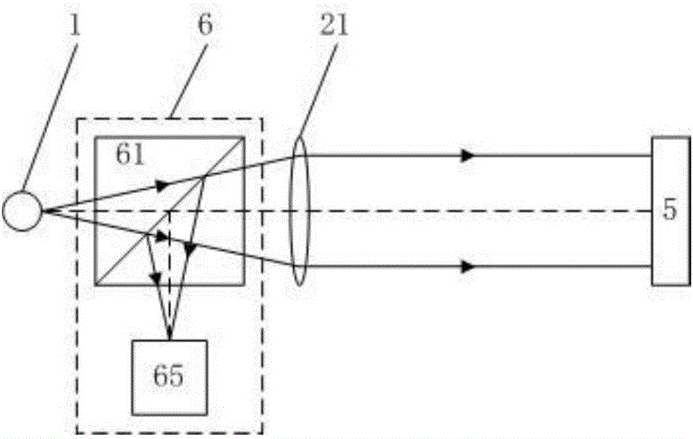
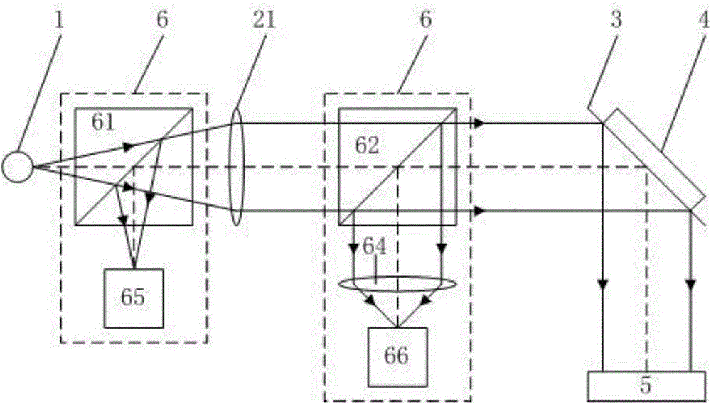
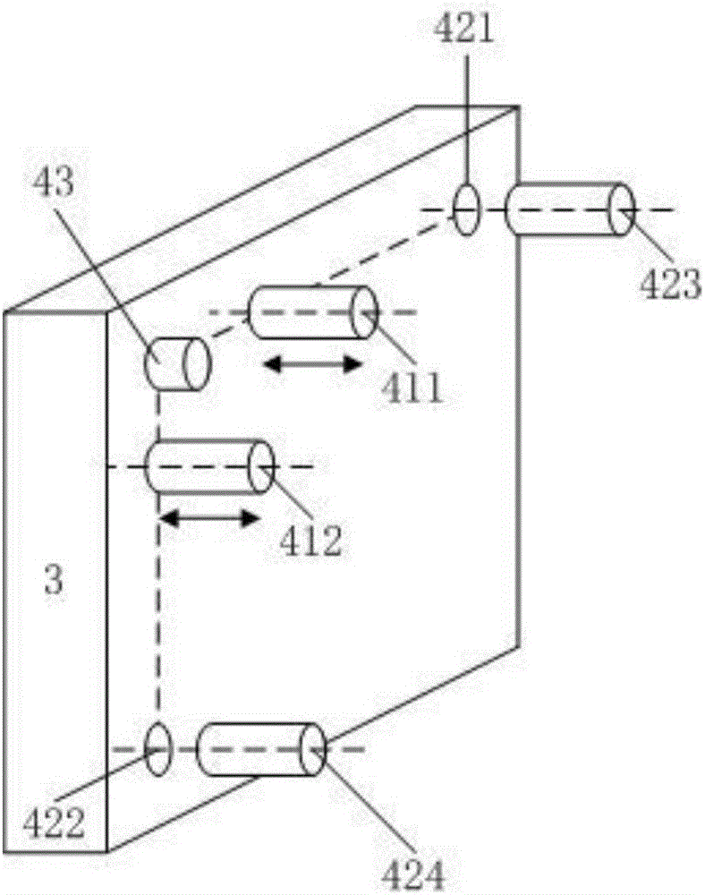
[0085] An autocollimation device with high precision, wide range and large working distance in this embodiment, the structural diagram is as follows figure 2 shown. The self-collimation device includes a light source 1, a transmissive collimator mirror 21, a reflector 3, and a feedback imaging system 6. The reflector 3 is provided with an angle adjustment measuring device 4; After the straight mirror 21 is collimated into a parallel light beam, it is reflected by the reflector 3 and incident on the surface of the measured object 5; the light beam reflected from the surface of the measured object 5 is then reflected by the reflective mirror 3 and collected by the feedback imaging system 6 imaging;

[0086] The feedback imaging system 6 includes an image sensor imaging system and a four-quadrant detector imaging system;

[0087] The image sensor ...

specific Embodiment 2

[0093] This embodiment is an embodiment of an autocollimation device with high precision, wide range and large working distance.

[0094] A kind of high-precision, wide range and large working distance autocollimation device of this embodiment is different from the specific embodiment 1 in the structure of the feedback imaging system 6; the structure of the feedback imaging system 6 of the present embodiment is in the following two forms A kind of:

[0095] First, the feedback imaging system 6 includes a first feedback beam splitter 61, and an image sensor 65 and a four-quadrant detector 66 carried by a guide rail 68, such as Figure 6 As shown; the guide rail 68 has two pause positions, one pause position makes the image sensor 65 image plane center correspond to the focus position of the transmissive collimator mirror 21, and the other pause position makes the four-quadrant detector 66 image plane center correspond to the transmission type The focus position of collimating ...

specific Embodiment 3

[0097] This embodiment is an embodiment of an autocollimation device with high precision, wide range and large working distance.

[0098] An autocollimation device with high precision, wide range and large working distance in this embodiment, the structural diagram is as follows Figure 8 shown. On the basis of the specific embodiment 1, a high precision, wide range and large working distance autocollimation device of this embodiment is also provided with a wavefront detection system 7 and a wavefront compensation system 8;

[0099] The wavefront detection system 7 includes a wavefront detection spectroscope 71 and an air disturbance wavefront detector 72; the wavefront detection spectroscope 71 is arranged between the reflector 3 and the measured object 5, and the air disturbance wavefront detector 72 is arranged on the reflected optical path of the wavefront detection spectroscope 71, and the mirror deformation wavefront detector 73 is arranged on the secondary reflected op...


PUM


Abstract

The invention belongs to the precision measurement technology field and the optical engineering field and especially relates to a high-precision, wide-range and large-work-distance auto-collimation device and a method thereof. The device is formed by a light source, a collimating mirror, a reflecting mirror and a feedback imaging system. In the method, through adjusting the reflecting mirror, a reflected light beam is returned to a feedback imaging system image plane center; and through using an angle deflection measurement apparatus on the reflecting mirror, an angle change of a measured object surface is acquired. Because the reflecting mirror is added on a traditional auto-collimation angle measurement system, a problem that measured object reflection light deviates the measurement system so that measurement can not be performed can be avoided. Under a same work distance, an auto-collimation work range is increased, or under the same work range, the work distance is increased. Besides, because of specific designs of the collimating mirror, the feedback imaging system, the reflecting mirror and the like, the structure is simple and manufacturing cost is low; under a low sampling frequency, measured precision is high and rapid measurement can be reached.

Description

technical field [0001] The invention belongs to the technical field of precision measurement and the field of optical engineering, and specifically relates to an autocollimation device and method with high precision, wide range and large working distance. Background technique [0002] In the fields of precision measurement technology, optical engineering, cutting-edge scientific experiments and high-end precision equipment manufacturing, there is an urgent need for large working range and high-precision laser self-collimation technology at a large working distance. It supports the development of technology and equipment in the above fields. [0003] In the field of precision measurement technology and instruments, the combination of laser autocollimator and circular grating can measure any line angle; the combination of laser autocollimation technology and polyhedral prism can measure surface angle and circular indexing; the maximum working distance From a few meters to hun...

Claims


Application Information

Patent Timeline
IPC IPC(8): G01B11/26G01C15/00
CPCG01B11/26G01C15/002
Inventor 谭欣然王超谭久彬
Owner HARBIN INST OF TECH
Why Eureka
Try Eureka