
High-temperature heat radiation and gas guide bearing

A technology of air guidance and bearings, which is applied to bearing components, shafts and bearings, mechanical equipment, etc., and can solve problems such as poor bearing lubrication, shortened service life, and leakage

Active Publication Date: 2016-12-21
ZHEJIANG LANXIANG BEARING
View PDF10 Cites 0 Cited by
  • Summary
  • Abstract
  • Description
  • Claims
  • Application Information

AI Technical Summary

Problems solved by technology

[0002] Bearings are precision supporting parts and basic parts. Most of the bearing materials are made of steel. If they are assembled in related mechanical hosts and work in a water environment, it is easy to cause rust and corrosion inside the bearing, resulting in reduced accuracy and stability. shortened lifespan
In order to make the bearing work normally in the water environment, some bearings are equipped with various waterproof protection devices on the outside to prolong the service life of the bearing. The typical structure is to set a bearing cover between the inner and outer rings of the bearing, for example The structure shown in the public technology named "dustproof and waterproof bearing" (CN105299057A); but in actual application, the high-speed operation of the bearing will generate high temperature inside, and the space surrounded by the bearing cap, bearing inner ring and bearing outer ring The air pressure rises, and under the action of high air pressure, the grease is easy to seep out from between the inner lip of the bearing cover and the inner ring, resulting in poor lubrication of the bearing and shortening the service life

Method used


Image

  • High-temperature heat radiation and gas guide bearing
  • High-temperature heat radiation and gas guide bearing
  • High-temperature heat radiation and gas guide bearing

Examples


Embodiment

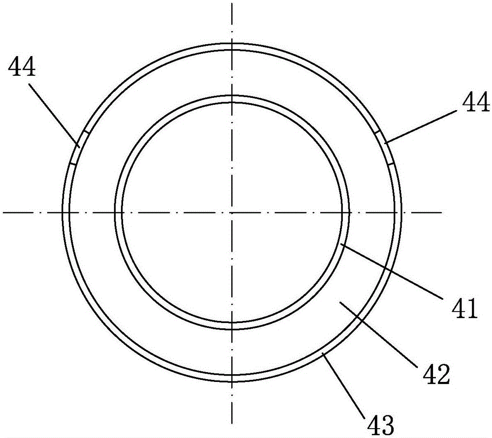
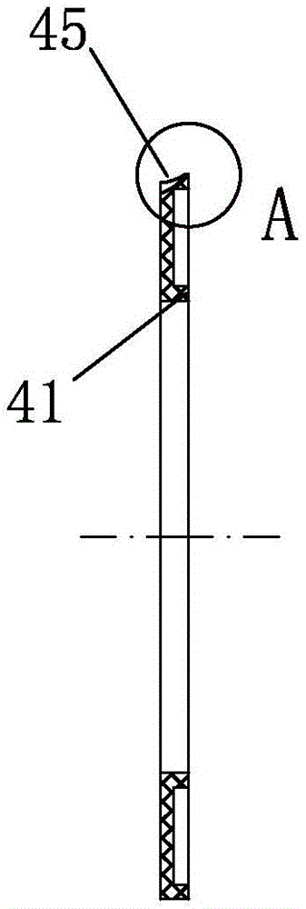
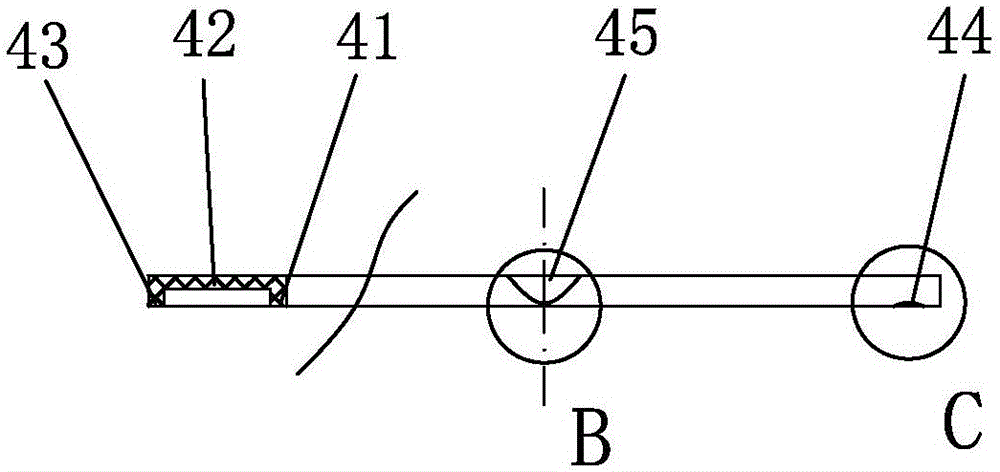
[0021] Embodiment: the high temperature heat dissipation air guide bearing of the present invention, as attached Figure 9 As shown, it includes an outer ring 1, an inner ring 2, steel balls 3 and a cage, and the steel ball 3 is arranged between the inner ring 2 and the outer ring 1 through the cage; There is a bearing cover 4, and the bearing cover 4 includes an annular plate 42 on which an outer lip 43 and an inner lip 41 are arranged.

[0022] as attached figure 1 , attached figure 2 , attached image 3 , attached Figure 4 , attached Figure 5 , attached Figure 6 , attached Figure 8 As shown, the outer corner of the joint between the outer lip 43 and the annular plate 42 is provided with a recessed groove 45; the upper part of the recessed groove 45 connects with the outer surface of the annular plate 42 to form an upper notch 451, and the lower part of the recessed groove 45 and the outer lip The outer peripheral walls of 43 meet to form a lower notch 452 , and ...


PUM


Abstract

The invention relates to a high-temperature heat radiation and gas guide bearing. The high-temperature heat radiation and gas guide bearing comprises an outer ring, an inner ring, a steel ball and a holder. A bearing cover is arranged between the inner ring and the outer ring and comprises an annular plate, and an outer lip side and an inner lip side are arranged on the annular plate. Sinking grooves are formed in the outer corner of the combination portion of the outer lip side and the annular plate. The upper portion of each sinking groove is connected with the outer surface of the annular plate to form an upper groove opening, the lower portion of each sinking groove is connected with the peripheral wall of the outer lip side to form a lower groove opening, and a distance exists between the bottom edge of each lower groove opening and the bottom face of the outer lip side. The groove walls of the sinking grooves can arch outwards under the internal pressure of the bearing, the internal space of the bearing is released, the volume of the internal closed space of the bearing is enlarged, and therefore the rising speed of the internal gas pressure of the bearing is reduced, the rising height of the internal gas pressure of the bearing is reduced, and lubricating grease is prevented from leaking out under high pressure accordingly.

Description

technical field [0001] The invention relates to a bearing, in particular to a high-temperature heat dissipation air guide bearing. Background technique [0002] Bearings are precision supporting parts and basic parts. Most of the bearing materials are made of steel. If they are assembled in related mechanical hosts and work in a water environment, it is easy to cause rust and corrosion inside the bearing, resulting in reduced accuracy and stability. Shortened lifespan. In order to make the bearing work normally in the water environment, some bearings are equipped with various waterproof protection devices on the outside to prolong the service life of the bearing. The typical structure is to set a bearing cover between the inner and outer rings of the bearing, for example The structure shown in the public technology named "dustproof and waterproof bearing" (CN105299057A); but in actual application, the high-speed operation of the bearing will generate high temperature inside...

Claims


Application Information

Patent Timeline
IPC IPC(8): F16C33/78
CPCF16C33/7816
Inventor 蓝德光吴魏华
Owner ZHEJIANG LANXIANG BEARING
Learn More