Control devices for internal combustion engines
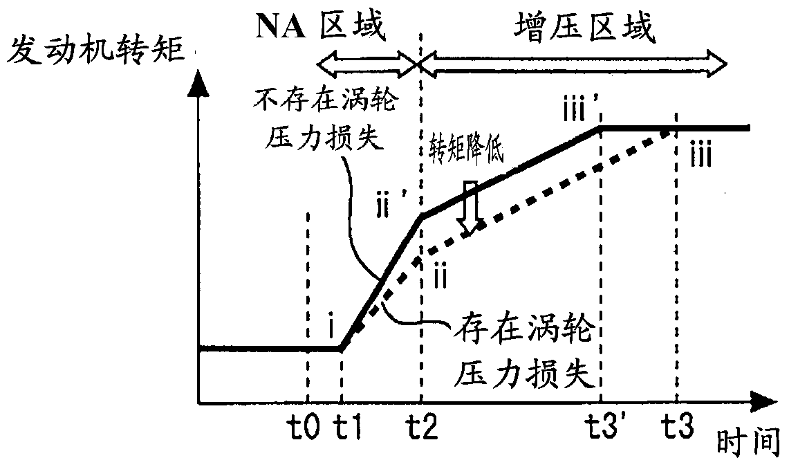
A technology of a control device and an internal combustion engine, which is applied in the direction of engine control, internal combustion piston engine, electrical control, etc., can solve the problems of prolonged engine torque time, increased power consumption, and insufficient pressure ratio of turbo compressors.
- Summary
- Abstract
- Description
- Claims
- Application Information
AI Technical Summary
Problems solved by technology
Method used
Image
Examples
Embodiment approach 1
[0049] [System Configuration of Embodiment 1]
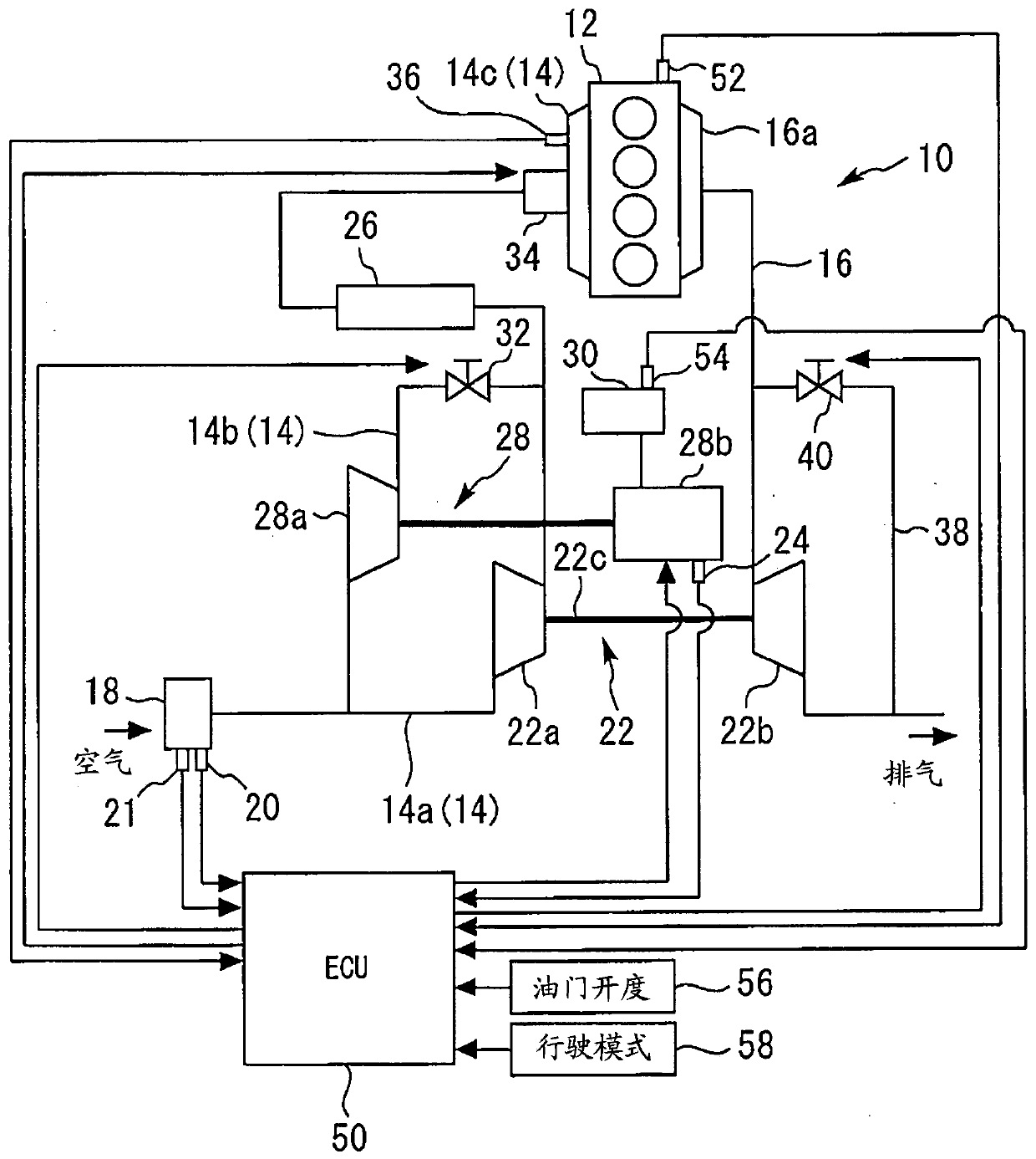
[0050] figure 1 It is a figure for schematically explaining the system structure of Embodiment 1 of this invention. figure 1 The illustrated internal combustion engine 10 has an internal combustion engine body 12 . As an example, the internal combustion engine 10 is a four-stroke inline four-cylinder type spark ignition engine (for example, a gasoline engine), which is mounted on a vehicle as a power unit thereof. The intake passage 14 and the exhaust passage 16 communicate with each cylinder of the internal combustion engine main body 12 .
[0051] The intake passage 14 has a first intake passage 14a through which air to be sucked into each cylinder of the internal combustion engine 10 flows. An air cleaner 18 is provided near the inlet of the first intake passage 14a. Attached to the air cleaner 18 are an air flow meter 20 that outputs a signal corresponding to the flow rate (mass flow rate) of intake air flowing through th...
Embodiment approach 2
[0102] Next, refer to Figure 8 ~ Figure 10 , Embodiment 2 of the present invention will be described. In the following description, as an example of the system configuration of Embodiment 2, reference figure 1 The system structure that has been discussed.
[0103] [Control of Embodiment 2]
[0104] (Summary of control in Embodiment 2)
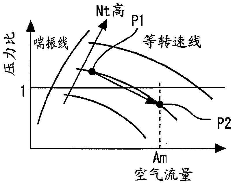
[0105] Figure 8 It is a figure for explaining the air supply operation in Embodiment 2 of this invention, and shows the compressor map of the turbo compressor 22a.
[0106] According to the air supply operation of Embodiment 1 described above, the flow rate of the air supplied by the electric compressor 28a is set to the auxiliary air flow rate C (=Am-B0), so that the electric compressor 28a ensures the air flow rate from the natural air intake area to the auxiliary air flow rate. The turbocompressor 22a does not function as a throttling device at the time of a torque increase request in the supercharging region, and the minimum necessar...
PUM
 Abstract
Description
Claims
Application Information
 - R&D Engineer
- R&D Manager
- IP Professional
- Industry Leading Data Capabilities
- Powerful AI technology
- Patent DNA Extraction
Browse by: Latest US Patents, China's latest patents, Technical Efficacy Thesaurus, Application Domain, Technology Topic, Popular Technical Reports.
© 2024 PatSnap. All rights reserved.Legal|Privacy policy|Modern Slavery Act Transparency Statement|Sitemap|About US| Contact US: help@patsnap.com


