
Control apparatus for internal combustion engine

A technology of a control device and an internal combustion engine, applied in the directions of engine control, internal combustion piston engine, electrical control, etc., can solve problems such as prolonged engine torque time, insufficient pressure ratio of turbo compressor, and increased power consumption.

Active Publication Date: 2016-12-21
TOYOTA JIDOSHA KK
View PDF6 Cites 10 Cited by
  • Summary
  • Abstract
  • Description
  • Claims
  • Application Information

AI Technical Summary

Problems solved by technology

[0008] In the situation where the difference between the actual intake flow rate and the target intake flow rate is confirmed, as in the technology described in Patent Document 1, the electric compressor is always used to assist the air flow rate corresponding to the difference. , there is concern that even if the responsiveness of the engine torque (acceleration responsiveness of the vehicle) can be improved, the power consumption will increase
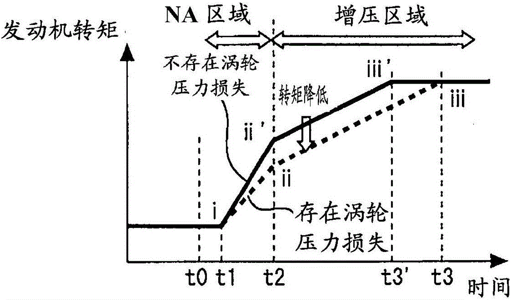
[0009] On the other hand, if the rotational speed of the turbo compressor is at a low rotational speed when the throttle valve is opened upon receipt of a torque increase request, there is a possibility that the intake air flow rate increases due to the opening of the throttle valve. Make the pressure ratio (= outlet pressure / inlet pressure) of the turbo compressor less than 1
As a result, the time required to achieve the requested engine torque is extended

Method used


Image

  • Control apparatus for internal combustion engine
  • Control apparatus for internal combustion engine
  • Control apparatus for internal combustion engine

Examples


Embodiment approach 1

[0049] [System Configuration of Embodiment 1]

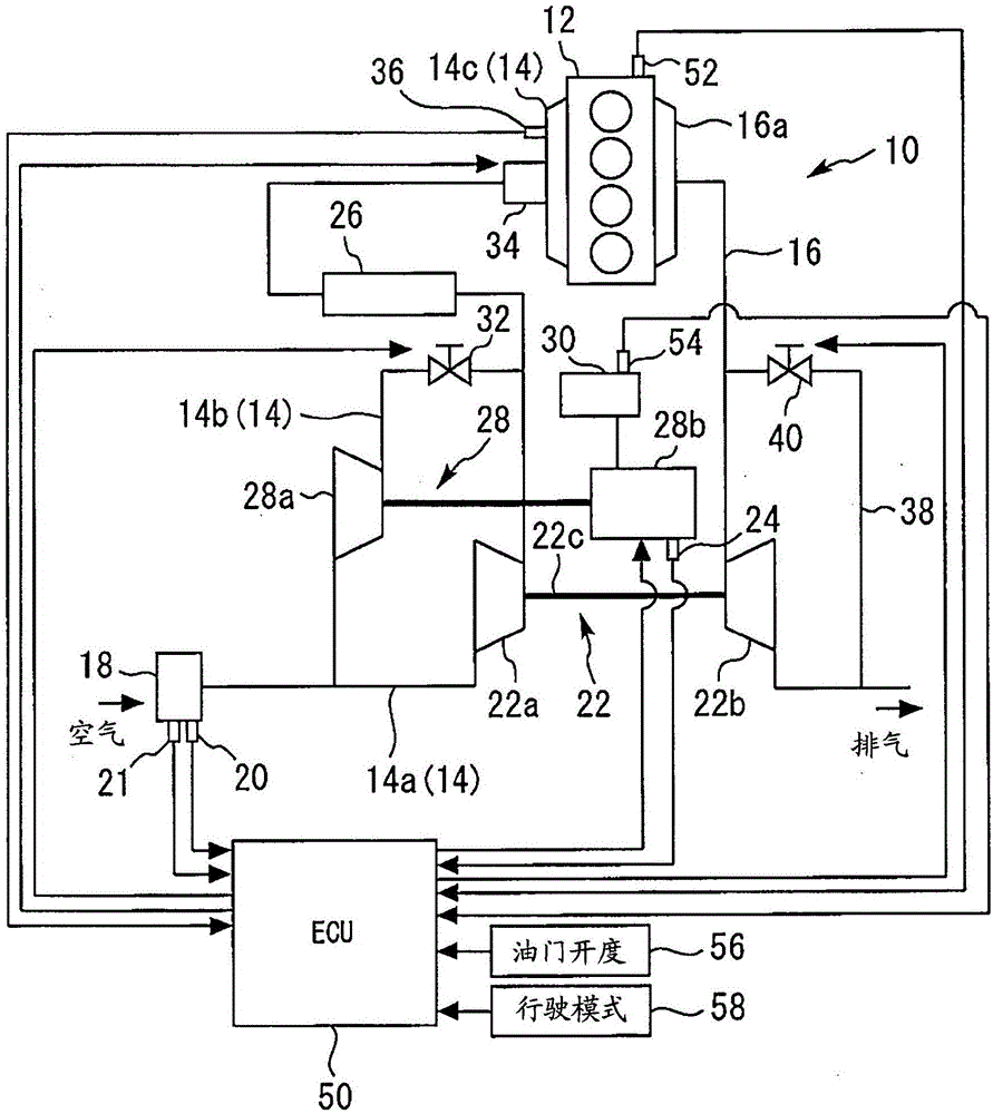
[0050] figure 1 It is a figure for schematically explaining the system structure of Embodiment 1 of this invention. figure 1 The illustrated internal combustion engine 10 has an internal combustion engine body 12 . As an example, the internal combustion engine 10 is a four-stroke inline four-cylinder type spark ignition engine (for example, a gasoline engine), which is mounted on a vehicle as a power unit thereof. The intake passage 14 and the exhaust passage 16 communicate with each cylinder of the internal combustion engine main body 12 .

[0051] The intake passage 14 has a first intake passage 14a through which air to be sucked into each cylinder of the internal combustion engine 10 flows. An air cleaner 18 is provided near the inlet of the first intake passage 14a. Attached to the air cleaner 18 are an air flow meter 20 that outputs a signal corresponding to the flow rate (mass flow rate) of intake air flowing through th...

Embodiment approach 2

[0102] Next, refer to Figure 8 ~ Figure 10 , Embodiment 2 of the present invention will be described. In the following description, as an example of the system configuration of Embodiment 2, reference figure 1 The system structure that has been discussed.

[0103] [Control of Embodiment 2]

[0104] (Summary of control in Embodiment 2)

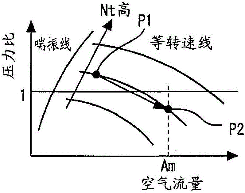
[0105] Figure 8 It is a figure for explaining the air supply operation in Embodiment 2 of this invention, and shows the compressor map of the turbo compressor 22a.

[0106] According to the air supply operation of Embodiment 1 described above, the flow rate of the air supplied by the electric compressor 28a is set to the auxiliary air flow rate C (=Am-B0), so that the electric compressor 28a ensures the air flow rate from the natural air intake area to the auxiliary air flow rate. The turbocompressor 22a does not function as a throttling device at the time of a torque increase request in the supercharging region, and the minimum necessar...


PUM


Abstract

A control apparatus is configured, after a torque increase request to increase an engine torque is made, to perform an air supply operation using an electric compressor where it is predicted that a pressure ratio of a turbo-compressor will become less than 1 after a throttle valve is opened accompanying the torque increase request, and, on the other hand, not to perform the air supply operation where it is predicted that the pressure ratio will not become less than 1 after the throttle valve is opened.

Description

technical field [0001] The present invention relates to a control device for an internal combustion engine, and more particularly to a control device for an internal combustion engine suitable as a device for controlling an internal combustion engine in which a turbo compressor and an electric compressor of a turbocharger are arranged in parallel on an intake air in the passage. Background technique [0002] Patent Document 1 discloses a supercharging system including a turbocharger and an electric compressor arranged in parallel in an intake passage of an internal combustion engine. This supercharging system is configured to operate the electric compressor at a rotational speed necessary to compensate the difference between the actual intake flow rate and the target intake flow rate when the actual intake flow rate of the internal combustion engine is insufficient. [0003] prior art literature [0004] Patent Document 1: Japanese Patent Laid-Open No. 2007-077854 [0005...

Claims


Application Information

Patent Timeline
IPC IPC(8): F02D43/00
CPCF02D43/00F02B2037/125F02D41/10F02B37/04F02B37/14F02B39/10F02D41/0007F02D2250/21F02B33/40Y02T10/12F02B37/007
Inventor 平山裕树
Owner TOYOTA JIDOSHA KK
Learn More