A self-resetting combined swing impact energy-dissipating shock-isolation device
A combined and self-resetting technology, which is applied in the direction of earthquake resistance, protective buildings/shelters, building types, etc., can solve the problems that cannot fully meet the earthquake resistance requirements of buildings, and achieve the effect of convenient repair, avoiding damage, and prolonging the service life
- Summary
- Abstract
- Description
- Claims
- Application Information
AI Technical Summary
Problems solved by technology
Method used
Image

Examples
Embodiment 1
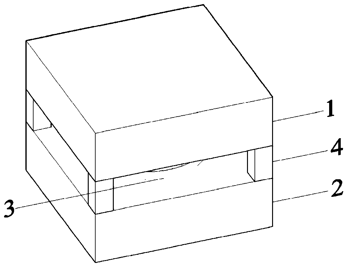
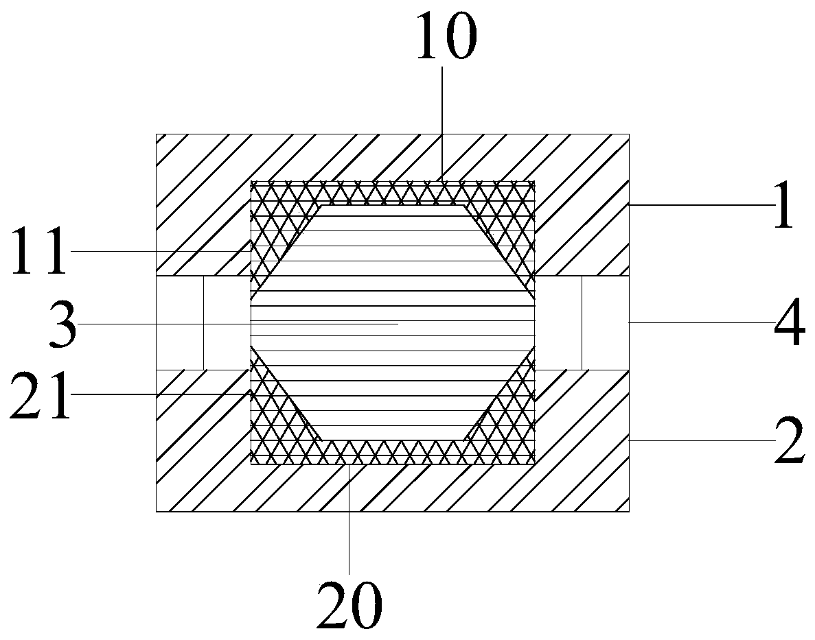
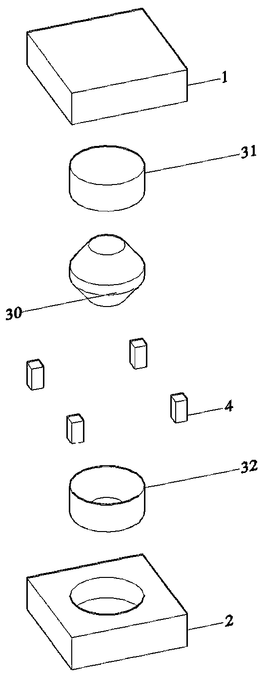
[0052] like Figure 1 to Figure 4 and Figure 21As shown, a self-resetting combined swing impact energy-dissipating shock-isolating device of the present invention includes a grooved upper support 1, a corresponding grooved lower support 2, and a middle of the two supports A freely placed columnar rocking impact energy dissipation block 3 and a group of two-stage tension limiting auxiliary devices 4. The upper support 1 and the lower support 2 are respectively connected with the upper structure and the foundation through embedded parts. The swing impact energy consumption block 3 can swing freely, and the depth of the swing impact energy consumption block 3 embedded in the grooves 13 and 23 of the upper support 1 and the lower support 2 is greater than that of the swing impact energy consumption block 3 on the contact surface 10, One side of 20 is the design value of the lifting height of the other side when the fulcrum is swinging. The second-stage tension limiting auxilia...
Embodiment 2
[0054] like Figure 5-8 and Figure 21 As shown, in the second preferred solution of the present invention, it includes a grooved upper support 1, a corresponding grooved lower support 2, and a freely placed columnar swing impact energy dissipation in the middle of the two supports. Block 3 and a group of two-stage tension limiting auxiliary devices 4. The upper support 1 and the lower support 2 are respectively connected with the upper structure and the foundation through embedded parts. The columnar rocking impact energy dissipation block 3 can swing freely, and the depth of the grooves 13 and 23 embedded in the upper support 1 and the lower support 2 is greater than that of the swinging impact energy dissipation block 3 on the contact surface 10 , One side of 20 is the design value of the lifting height of the other side when the fulcrum is swinging. The second-stage tension limiting auxiliary device 4 is fixed on the periphery of the upper support 1 and the lower suppor...
Embodiment 3
[0056] like Figure 9-12 and Figure 22 As shown, in the third preferred solution of the present invention, it includes a grooved upper support 1, a corresponding grooved lower support 2, and a freely placed columnar swing impact loss in the middle of the two supports. Energy block 3 and a group of two-stage tension limiting auxiliary devices 4. The upper support 1 and the lower support 2 are respectively connected with the upper structure and the foundation through embedded parts. The columnar rocking impact energy consumption block 3 can swing freely, and the depth of the grooves 13, 23 embedded in the upper support 1 and the lower support 2 is greater than that of the rocking impact energy consumption block 3 on the contact surface 10, One side of 20 is the design value of the lifting height of the other side when the fulcrum is swinging. The second-stage tension limiting auxiliary device 4 is fixed on the periphery of the upper support 1 and the lower support 2 through ...
PUM
 Abstract
Description
Claims
Application Information
 - R&D
- Intellectual Property
- Life Sciences
- Materials
- Tech Scout
- Unparalleled Data Quality
- Higher Quality Content
- 60% Fewer Hallucinations
Browse by: Latest US Patents, China's latest patents, Technical Efficacy Thesaurus, Application Domain, Technology Topic, Popular Technical Reports.
© 2025 PatSnap. All rights reserved.Legal|Privacy policy|Modern Slavery Act Transparency Statement|Sitemap|About US| Contact US: help@patsnap.com