Monitoring big data storage platform network architecture
A technology of big data storage and network architecture, which is applied in the field of monitoring the network architecture of big data storage platforms, can solve problems such as low value density, network capacity and network bandwidth limitations, and single point of failure, so as to reduce demand, increase network capacity and The effect of reducing bandwidth and reducing network energy consumption
- Summary
- Abstract
- Description
- Claims
- Application Information
AI Technical Summary
Problems solved by technology
Method used
Image
Examples
Embodiment 1
[0024] A monitoring big data storage platform network architecture, its external storage adds an optical switching network to the existing structure, the optical switching network and the electrical switching network are used for collaborative communication, making full use of the advantages of high bandwidth and high transmission efficiency of the optical network, increasing network capacity and bandwidth.
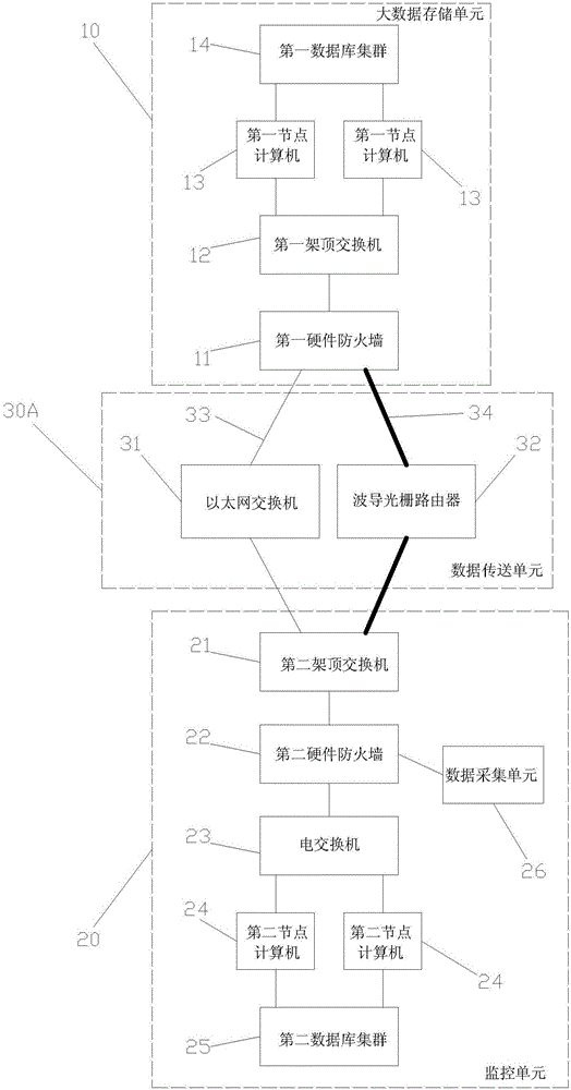
[0025] Please refer to figure 1 As shown, a monitoring big data storage platform network architecture, which includes a big data storage unit 10 and a monitoring unit 20, the monitoring unit 20 transmits its monitoring data to the big data storage unit 10 through a data transmission unit 30A, and completes the monitoring data external storage.
[0026] The monitoring unit 20 has a storage device for realizing the internal storage of monitoring data. Specifically, the monitoring unit 20 includes a second top-of-rack switch 21, a second hardware firewall 22, one or more da...
Embodiment 2
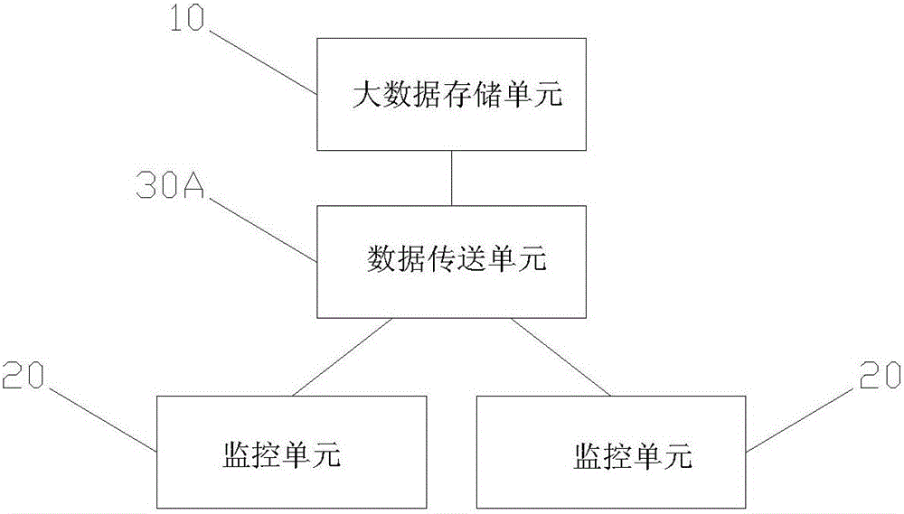
[0031] Embodiment 2 is an improvement on the basis of Embodiment 1, which can realize the external storage of data of multiple monitoring units 20 at the same time, please refer to figure 2 As shown, here two monitoring units 20 are taken as an example, the internal storage of each monitoring unit 20 is stored through its own second database cluster 25, and the external storage is completed through the data transmission unit 30A.
Embodiment 3
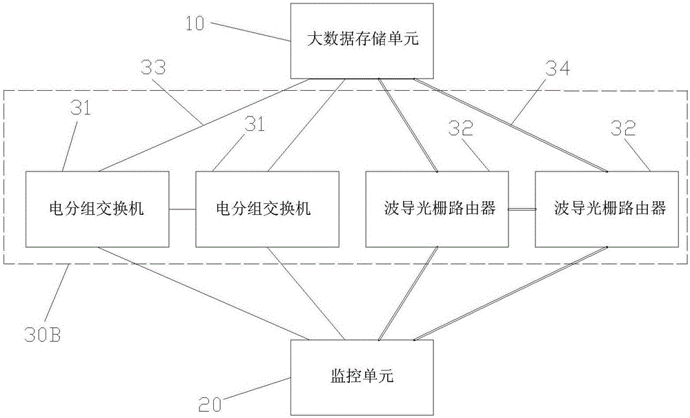
[0033] The third embodiment increases the redundancy of the Ethernet switch and the WG router on the basis of the first embodiment, please refer to image 3 As shown, there are two Ethernet switches and two WG routers, forming a data transmission unit 30B. Two Ethernet switches 31 are respectively used as main and standby Ethernet switches, and two waveguide grating routers 32 are respectively used as main and standby grating routers. The two Ethernet switches 31 are connected by optical fiber cables 33. When the main Ethernet switch fails In the case of starting the standby Ethernet switch to complete the data transmission. Similarly, the two WG grating routers 32 are connected through a wavelength division multiplexing optical fiber link 34, and in the event of failure of the main WG grating router, the backup WG grating router is activated to complete data transmission. Of course, in order to further prevent network congestion in the process of data transmission, multiple ...
PUM
 Abstract
Description
Claims
Application Information
 - R&D
- Intellectual Property
- Life Sciences
- Materials
- Tech Scout
- Unparalleled Data Quality
- Higher Quality Content
- 60% Fewer Hallucinations
Browse by: Latest US Patents, China's latest patents, Technical Efficacy Thesaurus, Application Domain, Technology Topic, Popular Technical Reports.
© 2025 PatSnap. All rights reserved.Legal|Privacy policy|Modern Slavery Act Transparency Statement|Sitemap|About US| Contact US: help@patsnap.com


