Temperature compensating circuit of power amplifier

A technology of temperature compensation circuit and power amplifier, applied to power amplifiers, improved amplifiers to reduce temperature/power supply voltage changes, amplifiers, etc., can solve problems such as difficult to achieve precise control of output power of power tubes

Active Publication Date: 2016-12-14
RDA MICROELECTRONICS SHANGHAICO LTD
View PDF5 Cites 23 Cited by
  • Summary
  • Abstract
  • Description
  • Claims
  • Application Information

AI Technical Summary

Problems solved by technology

This document is mainly applicable to self-bias circuits or voltage bias methods, a

Method used


Image

  • Temperature compensating circuit of power amplifier
  • Temperature compensating circuit of power amplifier
  • Temperature compensating circuit of power amplifier

Examples


Embodiment Construction

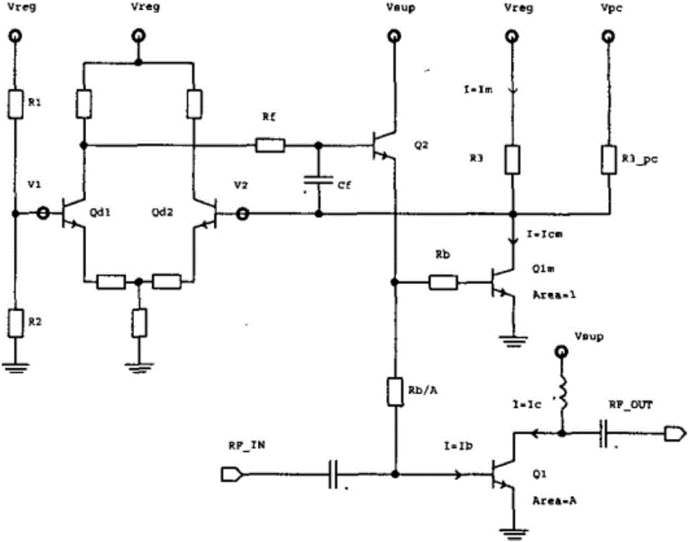
[0029] see Figure 4, which is Embodiment 1 of the power amplifier and its bias circuit of the present application. The whole circuit is composed of current bias circuit, temperature compensation circuit and amplifier circuit. The current bias circuit is used to provide a constant bias current Is, which can be understood as a current source, and can also be realized by a voltage source or a self-bias circuit. The temperature compensation circuit provides the temperature-compensated bias current ipwr for the base of the power transistor Q1 after performing temperature compensation on the bias current Is. The temperature compensation includes three aspects: first, when the power tube is working normally and below the threshold temperature, the collector current change of the power tube is positively correlated with the temperature change; second, when the power tube is working normally and below the threshold temperature In the above, the collector current change of the power ...


PUM


Abstract

This application discloses a temperature compensating circuit of a power amplifier. The temperature compensating circuit performs temperature compensation on a constant bias current; or converts a constant bias voltage into a current, performs temperature compensation, and then provides a base electrode of a power tube with a temperature-compensated bias current. The temperature compensation comprises: when the power tube works normally and is at a temperature below a threshold temperature, making a current variation of the collector electrode of the power tube positively correlated with a temperature variation; and when the power tube works normally and is at a temperature above the threshold temperature, or when the power tube is mismatched and works abnormally, making the current variation of the collector electrode of the power tube negatively correlated with the temperature variation. According to the temperature compensating circuit of the power amplifier, reliability problems such as an output power variation, a stability variation, linearity deterioration, and overheating and overburning caused when a temperature of the power amplifier varies are resolved.

Description

technical field [0001] The present application relates to a bias circuit of a power amplifier, in particular to a temperature compensation circuit therein. Background technique [0002] RF power amplifiers usually use heterojunction bipolar transistors (HBT), complementary metal oxide semiconductor transistors (CMOS), high electron mobility transistors (HEMT), etc. as amplifying transistors, called power transistors. The power tube requires a certain DC voltage and / or DC current during operation, which is called biasing. If the bias circuit provides DC voltage for the power tube, it is called voltage bias mode. If the bias circuit provides DC current for the power tube, it is called current bias mode. Most of the existing RF power amplifiers use voltage bias. However, new generation communication standards such as 4G and 5G have put forward new performance requirements for RF power amplifiers. Traditional voltage bias RF power amplifiers can no longer meet the new performa...

Claims


Application Information

Patent Timeline
IPC IPC(8): H03F1/30H03F3/19H03F3/24
CPCH03F1/30H03F3/19H03F3/245H03F2200/447H03F2200/451
Inventor 林甲富柯庆福陈文斌贾斌
Owner RDA MICROELECTRONICS SHANGHAICO LTD
Why Eureka
Try Eureka