Motor and its rotor structure

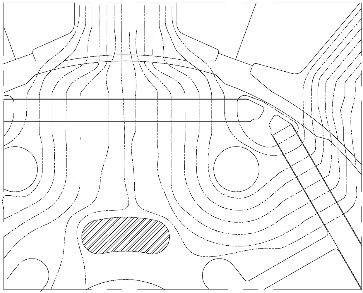
A technology of rotor structure and rotor body, applied in the direction of magnetic circuit shape/style/structure, electromechanical devices, electrical components, etc., can solve the problems of inability to improve motor output, disordered distribution of magnetic lines of force, etc., to eliminate the disorder of magnetic lines of force, fundamental wave amplitude The effect of improving and improving the effective torque

Active Publication Date: 2019-02-05
ZHUHAI LANDA COMPRESSOR +1
View PDF4 Cites 0 Cited by
  • Summary
  • Abstract
  • Description
  • Claims
  • Application Information

AI Technical Summary

Problems solved by technology

[0003] Based on this, it is necessary to solve the problem that the yoke of the current rotor structure cannot improve the output of the motor due to the disordered distribution of the magnetic force lines in the yoke, and provide a rotor that can effectively eliminate the problem of the disordered distribution of the magnetic force lines in the yoke and improve the effective torque of the motor. structure, and also provides a motor containing the above-mentioned rotor structure

Method used


Image

  • Motor and its rotor structure
  • Motor and its rotor structure
  • Motor and its rotor structure

Examples


Embodiment Construction

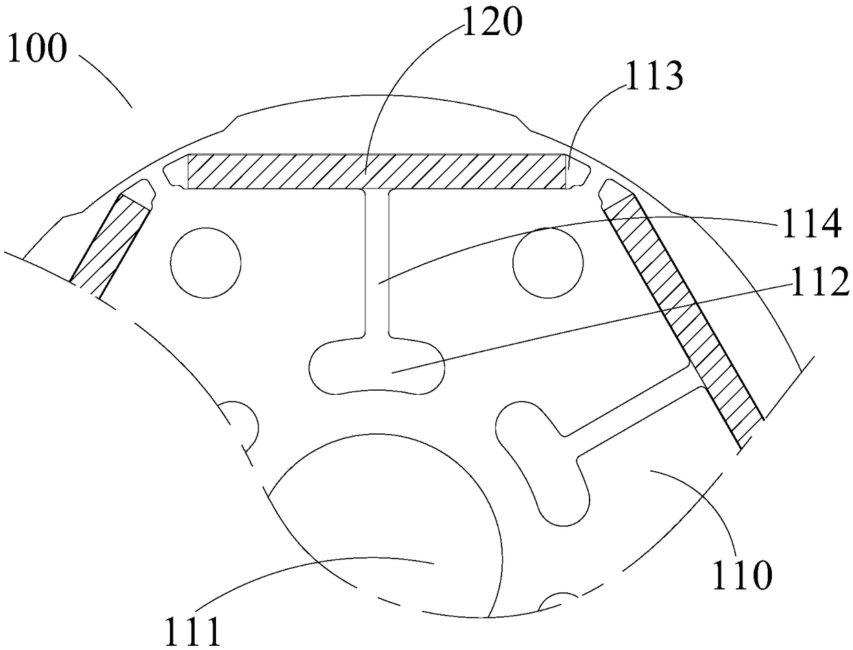
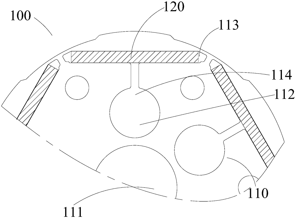
[0036] In order to make the purpose, technical solution and advantages of the present invention clearer, the motor and its rotor structure of the present invention will be further described in detail through the following embodiments and in conjunction with the accompanying drawings. It should be understood that the specific embodiments described here are only used to explain the present invention, not to limit the present invention.

[0037] In describing the present invention, it should be understood that the terms "center", "longitudinal", "transverse", "length", "width", "thickness", "upper", "lower", "front", " Back", "Left", "Right", "Vertical", "Horizontal", "Top", "Bottom", "Inner", "Outer", "Axial", "Radial", "Circumferential", etc. The indicated orientation or positional relationship is based on the orientation or positional relationship shown in the drawings, and is only for the convenience of describing the present invention and simplifying the description, rather ...


PUM


Abstract

The invention provides a rotor structure which comprises a rotor body, wherein a rotating shaft hole is formed in the rotor body; a plurality of air holes which are distributed around the rotating shaft hole are also formed in the rotor body; a plurality of magnet accommodating slots used for accommodating the rotor magnets are arranged on the rotor body; the magnet accommodating slots are distributed around the outer side of the air holes and are arranged on edge positions of the rotor body; magnetic line settling slots which penetrate through the rotor body along the axial direction are also formed on the rotor body; the magnetic line settling slots are located between the magnet accommodating slots and the air holes. The magnetic line settling slots are used for effectively solving the problem of disorder magnetic lines of a yoke part of the rotor body, so that the rotor structure provided by the invention compared with the traditional structural rotor is capable of increasing the fundamental current amplitude of the induced voltage in a stator winding and obviously increasing the effective torque of the motor. The invention also provides the motor.

Description

technical field [0001] The invention relates to the technical field of motor equipment, in particular to a motor and its rotor structure. Background technique [0002] At present, in permanent magnet synchronous motors, for permanent magnet synchronous motors with 3n (n=2, 3, 4...) slots in the motor stator and 2n (n=2, 3, 4...) poles in the rotor, the rotor structure is passed in The two ends of the rare earth magnet are provided with magnetic isolation holes, and a q-axis groove is provided in the q-axis direction. This structure can effectively reduce magnetic flux leakage, improve the waveform of the air gap magnetic field, and reduce the induced voltage in the stator winding. High harmonics, reduce cogging torque, reduce noise and vibration. However, the distribution of magnetic force lines in the rotor yoke of this structure is relatively disordered, and the effective fundamental wave voltage induced in the stator winding is relatively low, so there is a problem that ...

Claims


Application Information

Patent Timeline
Patent Type & Authority Patents(China)
IPC IPC(8): H02K21/14H02K21/02H02K1/27
CPCH02K1/274H02K21/02H02K21/14
Inventor 胡健华范少稳谢利昌
Owner ZHUHAI LANDA COMPRESSOR
Why Eureka
Try Eureka