
Energy-saving relay

A technology of relays and energy-saving circuits, applied in relays, circuits, electrical components, etc., can solve problems such as energy loss, safety hazards, and increased coil temperature rise

Active Publication Date: 2016-12-14
SANYOU CORP LTD
View PDF5 Cites 3 Cited by
  • Summary
  • Abstract
  • Description
  • Claims
  • Application Information

AI Technical Summary

Problems solved by technology

[0003] 1. The temperature rise of the coil increases, which brings potential safety hazards;
[0004] 2. Serious loss of energy consumption

Method used


Image

  • Energy-saving relay
  • Energy-saving relay

Examples


Embodiment Construction

[0022] The technical solution of the present invention will be described in detail below in conjunction with the accompanying drawings.

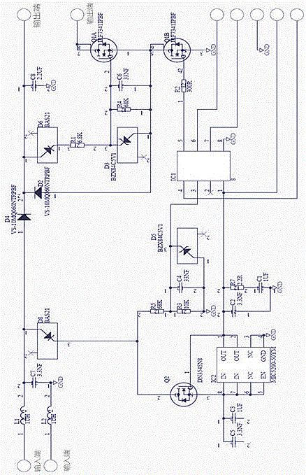
[0023] An energy-saving relay, comprising a relay body and an energy-saving circuit connected in series with a coil in the relay body, the energy-saving circuit comprising a voltage stabilization filter sampling module, an IC power management module, an IC pulse control module and a MOS tube switching circuit module;

[0024] The voltage stabilization filter sampling module is used to adjust the input voltage to less than 5V (that is, within the range voltage of the IC pulse control module); since the input voltage is a high voltage, the voltage stabilization filter sampling module adjusts the high voltage to the range voltage of the control chip Inside (within 5V), the control chip adjusts the duty cycle according to the sampling of the input voltage. The higher the input voltage, the smaller the duty cycle, and the lower the input voltage, ...


PUM


Abstract

The invention belongs to the field of relays, and specifically relates to an energy-saving relay. The relay comprises a relay body and an energy-saving circuit serially connected with a coil in the relay body, wherein the energy-saving circuit comprises a voltage stabilizing filter sampling module, an IC (Integrated Circuit) power management module, an IC pulse control module and an MOS (Metal Oxide Semiconductor) transistor on-off circuit module; the voltage stabilizing filter sampling module is used for adjusting the input voltage to be less than 5V; the IC power management module is used for converting the input voltage to stable 5V voltage and supplying the 5V voltage to the IC pulse control module; the IC pulse control module is used for controlling the on / off and on / off time of the energy-saving circuit; and the MOS transistor on-off circuit module is used for converting output voltage into input voltage. The relay has the advantages that after contacts of the relay are completely attracted, maintaining voltage is supplied to the relay in a pulse mode, so that the effective value of the external input voltage is greatly reduced, the energy loss when the relay is maintained is reduced, and energy is saved.

Description

technical field [0001] The invention belongs to the field of relays, in particular to an energy-saving relay. Background technique [0002] Because the high-voltage DC relay is used in a high-voltage environment, the distance between the contacts will be very large. The relay coil needs a lot of power to pull in to ensure that the product can be pulled in smoothly and reliably. After the relay is successfully pulled in, it maintains power. It is not necessary to maintain such a large pull-in power all the time, and there is a huge difference between the hold power and the pull-in power. If the pull-in power is always used to maintain the "on" of the relay, the following defects will occur: [0003] 1. The temperature rise of the coil increases, which brings potential safety hazards; [0004] 2. Serious loss of energy consumption. Contents of the invention [0005] In order to overcome the shortcomings and deficiencies existing in the prior art, the present invention pro...

Claims


Application Information

Patent Timeline
IPC IPC(8): H01H47/02
CPCH01H47/02
Inventor 宋朝阳
Owner SANYOU CORP LTD
Learn More