An emergency stop button and its assembly method
An integrated, matching technology, applied in electrical components, electrical switches, circuits, etc., can solve problems affecting product service life, impact force transmission, etc., to save product cost, improve product performance, and simplify assembly.
- Summary
- Abstract
- Description
- Claims
- Application Information
AI Technical Summary
Problems solved by technology
Method used
Image

Examples
Embodiment 1
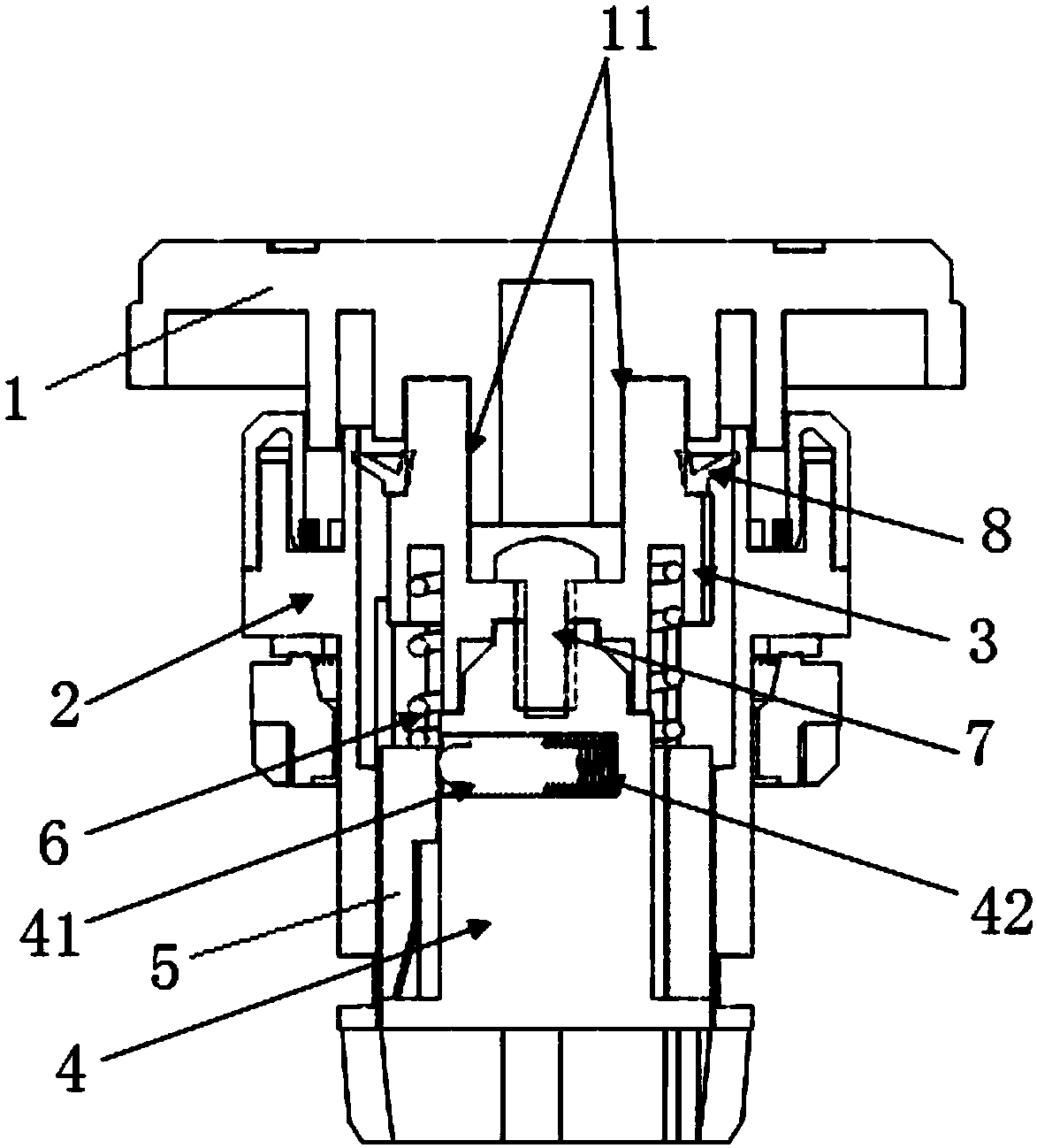
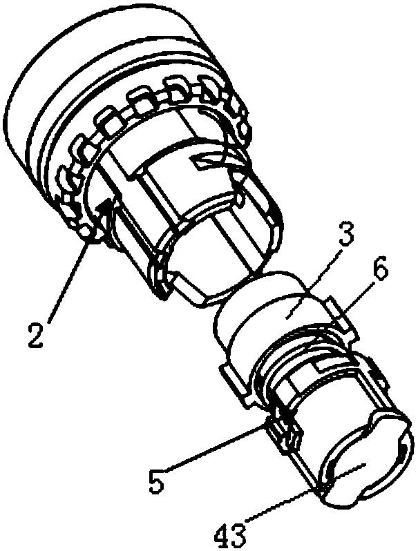
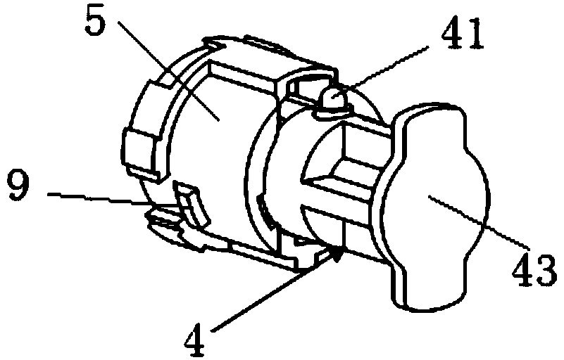
[0049] An emergency stop button, such as Figure 1~2 As shown, it includes a button 1, a casing 2 and an integrated push rod assembly, the casing 2 is set outside the integrated push rod assembly, and the integrated push rod assembly includes a transmission rod 3, a push rod 4, a shaft sleeve 5 and a torsion spring 6, The button 1, the transmission rod 3 and the push rod 4 are connected sequentially from top to bottom, the bushing 5 is set outside the push rod 4, and is fixed with the casing 2, and the push rod 4 and the bushing 5 are respectively provided with a stop gear assembly and a stop gear assembly. Gear chute, torsion spring 6 is arranged between transmission rod 3 and axle sleeve 5.
[0050]In this example, a push rod hole is provided on the outer wall of the push rod 4 , the stop gear assembly is composed of a stop gear 41 and a spring 42 arranged in the push rod hole, and the stop gear chute is arranged on the inner side wall of the shaft sleeve 5 . The bottom of ...
Embodiment 2
[0064] The emergency stop button of this embodiment is basically the same as that of Embodiment 1, the difference is that the cross-section of the key stroke limiting rib 12 of the key 1 of this embodiment is circular, and the cross section of the key stroke limiting groove is circular. shape, and the protruding portion 11 with an external thread is arranged at the center of the cross section of the stroke limiting rib 12 of the key. The bottom of the key 1 is also provided with an actuation groove matching the shape of the top of the transmission rod 3. When the key 1 and the transmission rod 3 are screwed together, the top of the transmission rod 3 is matched with the actuation groove. There is also an annular rib 13 between the protruding portion 11 with external thread and the key travel limiting rib 12, and the actuating groove is an annular rib formed between the outer side wall of the annular rib 13 and the inner side wall of the key travel limiting rib 12. grooves, suc...
Embodiment 3
[0066] An emergency stop button of this embodiment is basically the same as that of Embodiment 2, the difference is that the stroke limiting rib 12 of this embodiment includes two convex ribs with an arc-shaped cross-section opposite to each other, and two The cross section of the convex rib is located on a circle, the cross section of the stroke limiting groove of the button is circular, and the protruding part 11 with external thread is arranged at the center of the cross section of the stroke limiting rib 12 of the button.
PUM
 Abstract
Description
Claims
Application Information
 - R&D
- Intellectual Property
- Life Sciences
- Materials
- Tech Scout
- Unparalleled Data Quality
- Higher Quality Content
- 60% Fewer Hallucinations
Browse by: Latest US Patents, China's latest patents, Technical Efficacy Thesaurus, Application Domain, Technology Topic, Popular Technical Reports.
© 2025 PatSnap. All rights reserved.Legal|Privacy policy|Modern Slavery Act Transparency Statement|Sitemap|About US| Contact US: help@patsnap.com