Linear transmission system

Active Publication Date: 2012-08-22
TBI MOTION TECH CO LTD
View PDF8 Cites 0 Cited by
  • Summary
  • Abstract
  • Description
  • Claims
  • Application Information

AI Technical Summary

Problems solved by technology

[0006] In this way, the heat dissipation effect of the ball screw device 2 is not good, so that the screw 21 will be thermally deformed due to temperature changes (usually the temperature rises by 1 ° C, and the screw 21 will elongate by 12 μm per 1 m), and cause the application of the ball screw device. 2 The production tolerance of the machining system is increased

Method used


Image

  • Linear transmission system
  • Linear transmission system
  • Linear transmission system

Examples


Embodiment Construction

[0051] Hereinafter, a linear transmission system according to a preferred embodiment of the present invention will be described with reference to the accompanying drawings, wherein the same components are denoted by the same symbols.

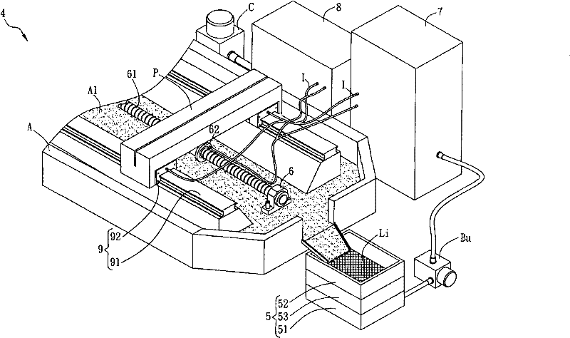
[0052] Please refer to figure 2 As shown, it is a schematic diagram of the linear transmission system 4 of this embodiment. The linear transmission system 4 includes a filter device 5 , a linear slide rail device 9 , a ball screw device 6 , a liquid temperature control device 7 and a gas temperature control device 8 .

[0053] The filter device 5 can have, for example, a filter screen 51 , a filter cotton or a filter cloth, and can also have a magnetic filter unit 52 and / or a centrifugal filter unit 53 . In this embodiment, the filter device 5 has a filter screen 51 , a magnetic filter unit 52 and a centrifugal filter unit 53 as an example for illustration, but this is not a limitation.

[0054] The linear slide rail device 9 has a slide rail...


PUM


Abstract

The invention discloses a linear transmission system, which comprises a filtering device, a linear slide rail device, a ball screw device, a liquid temperature control device and a gas temperature control device, wherein the linear slide rail device is provided with a slide rail and a sliding block which is arranged on the slide rail in a sliding way; the ball screw device is arranged adjacent to the linear slide rail device and is provided with a screw rod and a ball nut; the ball nut is sleeved and arranged in the screw rod in the sliding way; the liquid temperature control device dips up liquid through the filtering device, the liquid is controlled at a preset temperature and is supplied to flowing between the screw rod and the ball nut; and the gas temperature control device provides a gas flowing between the screw rod and the ball nut. The gas is controlled at the preset temperature. The gas temperature control device mixes the gas and the liquid through the tube body, and the gas and the liquid are filled between the screw and the ball nut after uniformly mixed.

Description

technical field [0001] The invention relates to a linear transmission system, in particular to a linear transmission system with a constant temperature control device. Background technique [0002] In various linear transmission systems, the rotation is converted into linear transmission through the cooperation of the screw and the nut of the ball screw device. In addition, the balls that can be driven circularly and the ball nut and the screw are matched with each other to reduce the friction between the ball nut and the screw, so that the linear transmission system runs more smoothly. [0003] Please refer to figure 1 As shown, it is a schematic diagram of the ball screw device 2 and the cooling device 3 of the existing linear transmission system 1 . The existing linear transmission system 1 includes a ball screw device 2 and a cooling device 3, which are connected to each other. The ball screw device 2 includes a screw 21 and a ball nut 22 , the ball nut 22 is sheathed...

Claims


Application Information

Patent Timeline
Patent Type & Authority Patents(China)
IPC IPC(8): F16H25/22F16H57/04
Inventor 李进胜杨进财
Owner TBI MOTION TECH CO LTD
Why Eureka
Try Eureka