Test method and test fixture for in-plane shear test of composite sheets
A composite material thin plate and test fixture technology, applied in the direction of analyzing materials, using stable shear force to test the strength of materials, measuring devices, etc., can solve the problems of high test cost, complicated loading equipment and supporting fixtures, etc., and achieve flexible loading , loading device simple effect
Active Publication Date: 2016-12-14
SHANGHAI JIAO TONG UNIV
View PDF8 Cites 18 Cited by
- Summary
- Abstract
- Description
- Claims
- Application Information
AI Technical Summary
Problems solved by technology
The main disadvantage of this method is that the loading equipment and supporting fixtures are complicated, and the test cost is high
[0008] The above three shear test methods have their own advantages and disadvantages. Therefor
Method used
View moreImage
Smart ImageViewing Examples

Examples
 PUM
 Abstract
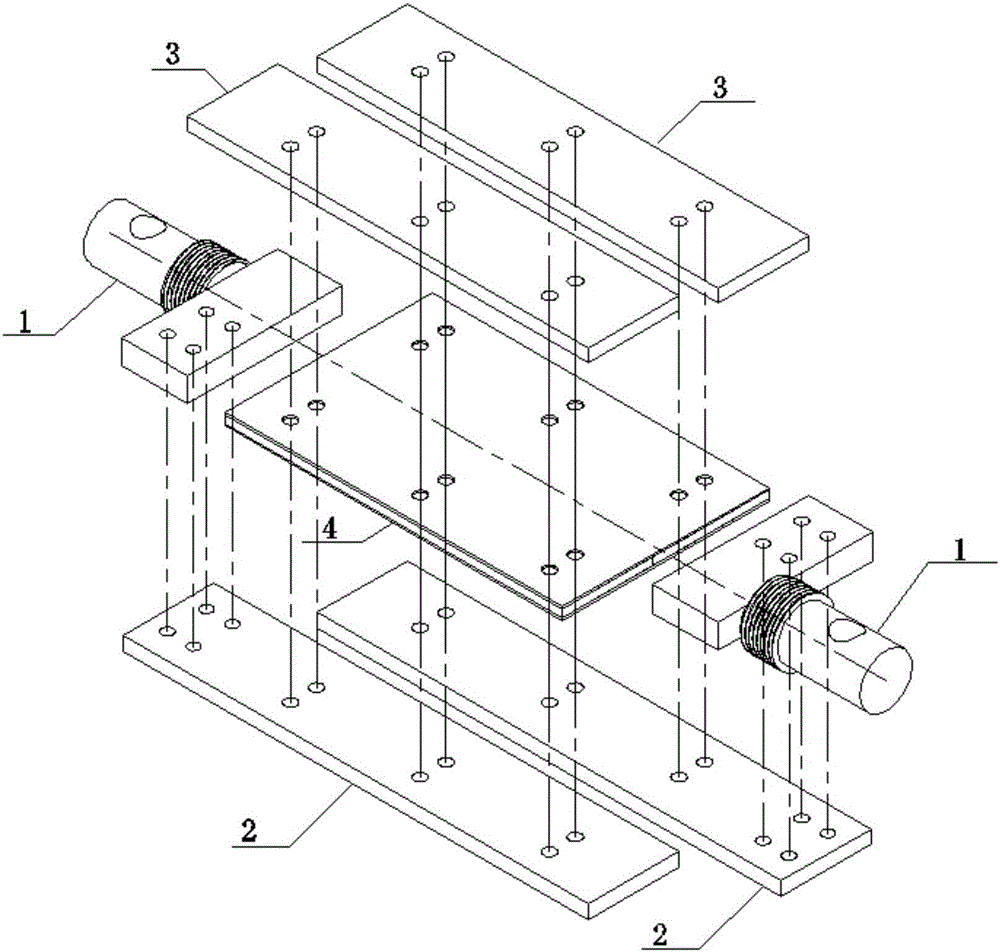
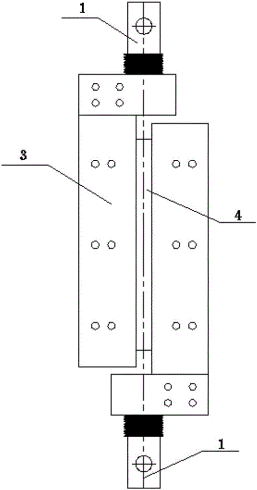
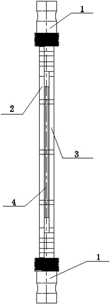
The invention discloses a test fixture for in-plane shear test of composite sheets. The test fixture comprises two groups of plugs, two groups of clamping plates and two groups of pressure plates. Each plug is in a T-shaped structure with a cylindrical connector at one end, the far end of each cylindrical connector is provided with a through hole, the near end of each cylindrical connector is provided with a thread used for fixed connection with a fixture port of a tester, and a connection plate is arranged at the other end of each plug and axially perpendicular to the corresponding cylindrical connector. Each clamping plate is fixedly connected with the connection plate of the corresponding plug, and the clamping plates and the pressure plates are provided with through holes in positional correspondence and used for fixing a to-be-tested sample through fasteners. The plugs, the clamping plates and the pressure plates are fixedly connected to two sides of the to-be-tested sample respectively. The invention further discloses a test method adopting the test fixture and a method for manufacturing the to-be-tested sample applicable to the test fixture. The test fixture is capable of realizing shear loading by the aid of the common tester and has advantages of simplicity of a loading device, loading flexibility, shear stress field uniformity and the like.
Description
technical field [0001] The invention relates to the technical field of engineering testing, in particular to an in-plane shear test fixture and test method for a composite material thin plate, which can be applied to the in-plane shear performance test of a composite material thin plate in engineering fields such as aviation, aerospace, and civil engineering. Background technique [0002] In the field of engineering technology, composite material sheet is the basic component of complex engineering structure, and its in-plane shear performance is an important design factor. [0003] At present, the test methods for in-plane shear properties of composite materials mainly include torsion method, off-axis tensile method and shear method. The torsion method follows the principle of the metal material shear performance test method. The most commonly used torsion method is the thin-walled cylinder torsion method. The test principle is to apply torque at both ends of the thin-walled...
Claims
Login to View More Application Information
Patent Timeline
 IPC IPC(8): G01N3/04G01N3/24
CPCG01N3/04G01N3/24G01N2203/0282G01N2203/0458
Inventor 陈务军康雄建张大旭房光强曹争利彭福军
Owner SHANGHAI JIAO TONG UNIV
Features
- Generate Ideas
- Intellectual Property
- Life Sciences
- Materials
- Tech Scout
- Unparalleled Data Quality
- Higher Quality Content
- 60% Fewer Hallucinations
Learn More Browse by: Latest US Patents, China's latest patents, Technical Efficacy Thesaurus, Application Domain, Technology Topic, Popular Technical Reports.
© 2025 PatSnap. All rights reserved.Legal|Privacy policy|Modern Slavery Act Transparency Statement|Sitemap|About US| Contact US: help@patsnap.com