Waste heat circulation system for direct air cooling tower

A circulation system and air cooling tower technology, applied in lighting and heating equipment, indirect carbon dioxide emission reduction, steam/steam condenser, etc., can solve the problems of waste heat source, temperature increase, thermal pollution, etc., to improve utilization rate and alleviate low temperature Corrosion and thermal pollution reduction effects

Inactive Publication Date: 2016-12-14
JILIN ELECTRIC POWER RES INST LTD
View PDF9 Cites 2 Cited by
  • Summary
  • Abstract
  • Description
  • Claims
  • Application Information

AI Technical Summary

Problems solved by technology

However, the temperature of the directly air-cooled air source has been greatly increased after passing through the water-cooling system, and direct discharge into the atmosphere will cause certain heat pollution and waste a lot of heat sources. Therefore, it is meaningful to design a system to recover waste heat and use heat exchange. major

Method used


Image

  • Waste heat circulation system for direct air cooling tower
  • Waste heat circulation system for direct air cooling tower
  • Waste heat circulation system for direct air cooling tower

Examples


Embodiment Construction

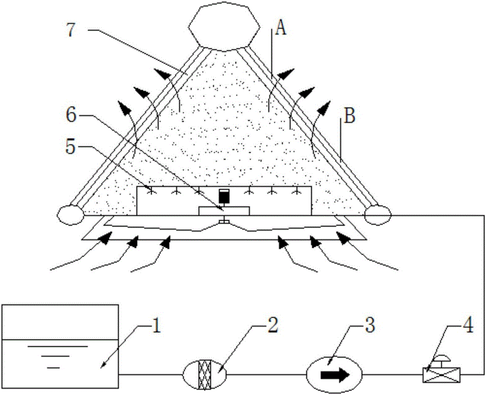
[0017] Such as figure 1 As shown, the present invention discloses a direct air-cooling tower waste heat circulation system. The front part of the system includes a desalinated water tank 1, a filter screen 2, a high-pressure pump 3 and an air-cooling unit 7 connected by pipelines in sequence, wherein the finned tubes in the air-cooling unit 7 The direct air-cooling tower structure is formed by slanting. There is a regulating valve 4 between the high-pressure pump 3 and the inside of the air-cooling tower. The fan 6 is located below the air-cooling tower. There is a nozzle 5 above the fan 6. The fan 6 sucks air at normal temperature from the outside. Flow through the nozzle 5 to the inside of the air cooling unit 7 above.

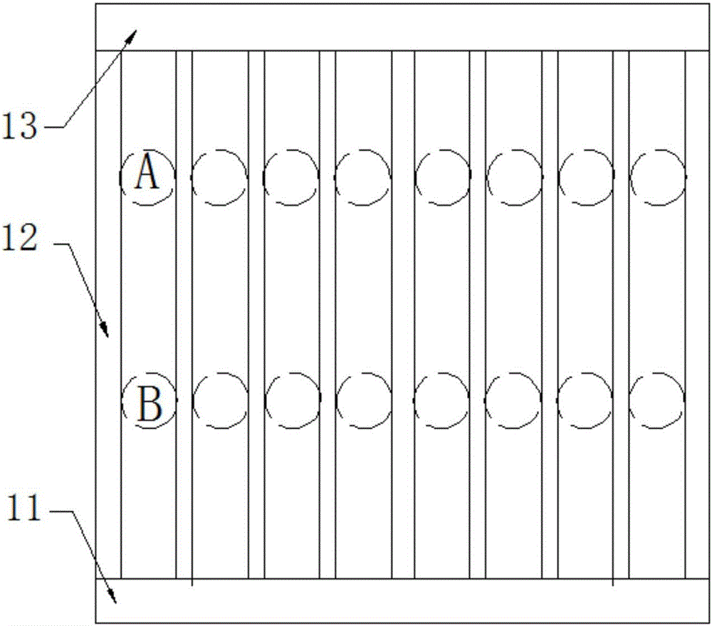
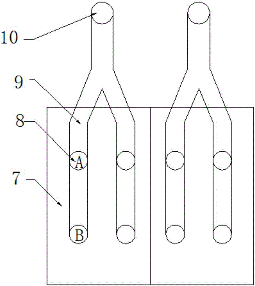
[0018] Such as figure 2 As shown, the air-cooling unit 7 located on the slope of the direct air-cooling tower is provided with a plurality of finned tubes 12 as condensers, the upper ends of the finned tubes 12 are connected with the exhaust steam pipeline...


PUM


Abstract

The invention discloses a waste heat circulation system for a direct air cooling tower. The waste heat circulation system is composed of a desalting water tank, a filter screen, a high-pressure pump, a regulating valve and an air cooling unit, wherein the desalting water tank, the filter screen, the high-pressure pump, the regulating valve and the air cooling unit are sequentially connected through pipelines. The air cooling unit is composed of a direct air cooling tower and a draught fan located on the lower portion of the interior of the air cooling unit, wherein the direct air cooling tower is formed by obliquely building fin pipes. Spray nozzles are further arranged above the draught fan. Air flows into the air cooling unit above through the spray nozzles. Multiple sets of air suction pipelines are arranged on the exterior of the direct air cooling tower in parallel and are fixed above the interval spaces of the adjacent fin pipes in the axial direction of the fin pipes correspondingly. Air suction openings are further formed in the lower portions of the air suction pipelines. Waste heat air between the fin pipes enters the air suction pipelines through the air suction openings. The output ends of the air suction pipelines are in butt joint with air feeder air feed pipelines of a boiler. Hot air at an outlet of a direct air cooling condenser is used for air used for boiler combustion, recycling of hot air at an outlet of the direct air cooling tower is achieved, the utilization rate of fuel is increased, thermal pollution is reduced, and the effects of energy conservation and emission reduction are achieved.

Description

technical field [0001] The invention belongs to the technical field of heat energy recovery equipment, is suitable for direct air-cooling generator sets, and in particular relates to a waste heat circulation system of a direct air-cooling tower. Background technique [0002] With the increasing scarcity of water resources in the world and the high attention to environmental protection issues, traditional thermal power water-cooled units are facing severe challenges due to the consumption of large amounts of water resources and certain negative impacts on the environment. In recent years, a large number of direct air-cooled generator sets have been put into operation in the northwestern region rich in coal and poor in water, which has alleviated the shortage of power generation caused by the lack of water resources in the local area, and has received good social benefits. The air-cooled unit adopts the air-condensing steam turbine to exhaust steam, which avoids the evaporatio...

Claims


Application Information

Patent Timeline
Patent Type & Authority Applications(China)
IPC IPC(8): F23L15/00F28B1/06
CPCF23L15/00F28B1/06Y02E20/34
Inventor 孙首衍赵金峰曹兴豆中州杨杉刘磊王行姚莹莹袁晋伟曹瀚文杨树彤
Owner JILIN ELECTRIC POWER RES INST LTD
Why Eureka
Try Eureka