
Integrated electronic hydraulic servo system

A hydraulic servo system, electric technology, applied in the direction of fluid pressure actuation system components, servo meter circuits, fluid pressure actuation devices, etc., can solve the problems of short working time and inability to start multiple times, to reduce power requirements, reduce Energy consumption and power requirements, the effect of reducing capacity requirements

Active Publication Date: 2016-12-14
BEIJING RES INST OF PRECISE MECHATRONICS CONTROLS +1
View PDF10 Cites 0 Cited by
  • Summary
  • Abstract
  • Description
  • Claims
  • Application Information

AI Technical Summary

Problems solved by technology

[0003] There are two major disadvantages in the servo system using gas as the primary energy source of the "gas-hydraulic" scheme: one is the short working time; the other is that it cannot be started multiple times
The working time of the servo system depends on the solid gas generator, and up to now, the working time of the gas generator does not exceed 100 seconds, so the working time of the servo system using gas as the primary energy source is less than 100 seconds; At the same time, the solid gas generator is a one-time working product, so there is an inherent defect that it cannot be started many times

Method used


Image

  • Integrated electronic hydraulic servo system
  • Integrated electronic hydraulic servo system
  • Integrated electronic hydraulic servo system

Examples


Embodiment Construction

[0024] In addition to the embodiments described below, the invention can be embodied in other embodiments or carried out in different ways. It is, therefore, to be understood that the invention is not limited to the details of construction of the components described in the following description or shown in the drawings. While only one embodiment is described here, the claims are not limited to that embodiment.

[0025] Specific embodiments of the present invention will be further described in detail below in conjunction with the accompanying drawings.

[0026] Such as figure 1 as shown,

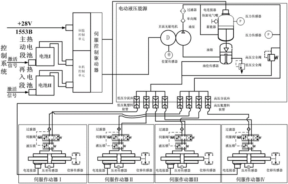
[0027] An integrated electro-hydraulic servo system, including electro-hydraulic energy, servo actuators, and servo control drivers, is installed in the servo control cabin; the servo battery uses a primary activation thermal battery, including an active thermal battery and a reentry thermal battery; The servo battery receives an activation signal through an electrical connector to provid...


PUM


Abstract

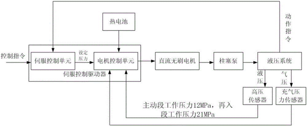
The invention belongs to an aircraft digital control electronic hydraulic servo system, and discloses an integrated electronic hydraulic servo system. According to the integrated electronic hydraulic servo system, a servo battery is activated by a control instruction to work and provide electric energy to a servo control drive; a direct-current brushless motor receives an instruction of the servo control drive to drive a plunger pump to operate; the servo control drive adopts energy high pressure as a control capacity, the output capacity of the plunger pump is adjusted by changing the rotation speed of a motor in real time, electronic hydraulic energy high-pressure closed loop control is achieved, and thus the purpose of energy power management can be achieved. After an oil pump is operated, high-pressure oil is divided into three paths, namely, one path flows to the oil cavity of an energy accumulator to store high-pressure oil in advance; a second path is introduced to the inlet of a high-pressure safety valve, and the high-pressure safety valve can be started to release the pressure if a servo mechanism energy control management loop has faults and the pressure of the high-pressure cavity is increased; a third path is used for providing oil supply paths for four servo actors through high-pressure connectors, the flow of the third path is controlled by a servo valve, and low-pressure oil is fed back to an oil tank through a low-pressure path after action of the servo actors.

Description

technical field [0001] The invention relates to a digital control electro-hydraulic servo system for aircraft. Background technique [0002] Electro-hydraulic servo mechanism, which is controlled by electrical signals, converts hydraulic energy into mechanical energy output. The working principle is to amplify the signal output by the servo amplifier in the control system through the high power of the servo valve and convert it into a control flow to drive the displacement of the actuator piston. , so that the control object deflects, and with the displacement of the piston, the feedback device or displacement sensor connected to it feeds back the signal of the piston displacement to the input terminal of the servo amplifier for comprehensive comparison to form a closed-loop position servo system. At present, it is more commonly used in aircraft air rudder maneuvering warheads using high-speed gas turbine pump electro-hydraulic servo system, such as the US Pershing II, the s...

Claims


Application Information

Patent Timeline
IPC IPC(8): F15B21/02
CPCF15B21/02F15B2211/00
Inventor 张小红曹泽生李娜曹英健王跃轩胡洋汤力
Owner BEIJING RES INST OF PRECISE MECHATRONICS CONTROLS
Learn More