
Plastic particle screening device

A screening device and technology for plastic particles, which are used in solid separation, separation of solids from solids by air flow, static electricity, etc., can solve problems such as easy upward movement, affecting the normal progress of screening work, and unfavorable passage of plastic particles through the screen.

Inactive Publication Date: 2016-12-14
重庆敏驰塑胶有限公司
View PDF0 Cites 13 Cited by
  • Summary
  • Abstract
  • Description
  • Claims
  • Application Information

AI Technical Summary

Problems solved by technology

[0003] Most of the existing screening devices use vibrating screens to allow plastic particles to pass through the screens. However, due to the high temperature of the newly prepared plastic particles, and the plastic is prone to static electricity after friction, when a large amount of plastic particles During centralized screening, it is very easy to cause adhesion between plastic particles, or stick to the screen, which seriously affects the normal screening work, reduces the efficiency of material selection, and increases the waste rate of plastic particles. At the same time , in order to cool down the plastic particles, it is also necessary to set up a fan to cool the plastic particles. However, due to the light weight of the plastic, it is easy to rise under the influence of the air flow, which makes it more difficult for the plastic particles to pass through the screen. Therefore, it is urgent to develop a A screening device invented to meet the needs of practical use

Method used


Image

  • Plastic particle screening device

Examples


Embodiment Construction

[0017] The present invention will be described in further detail below by means of specific embodiments:

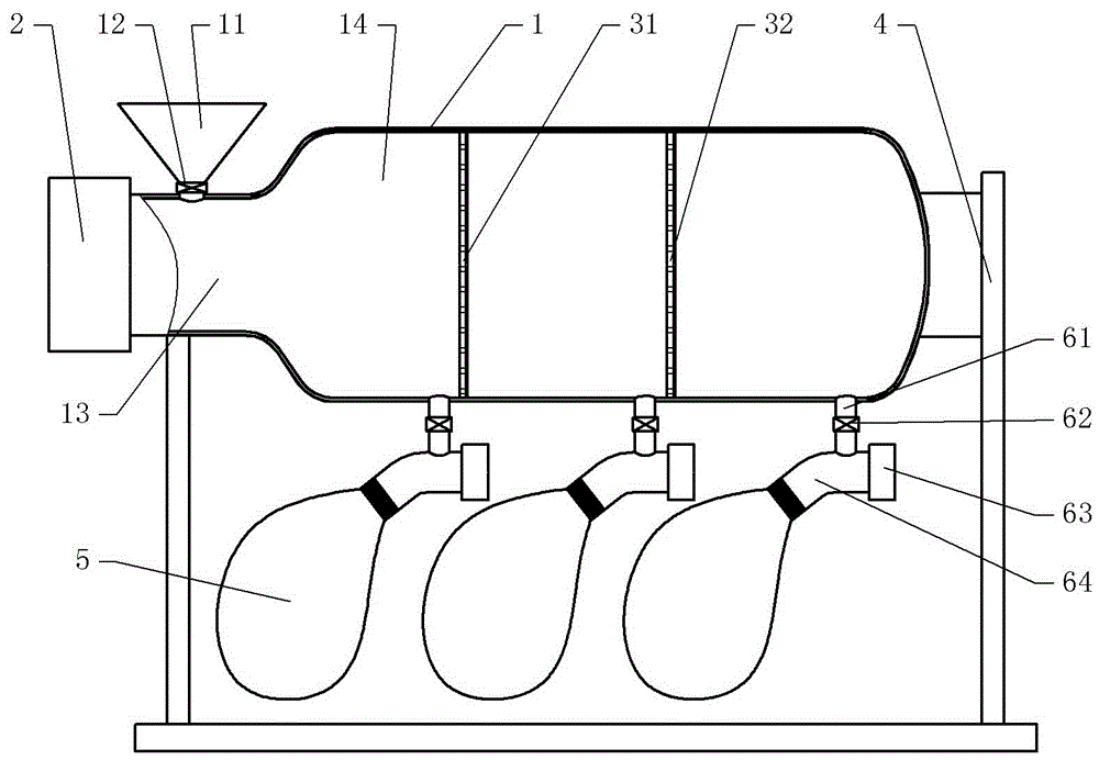
[0018] The reference signs in the drawings of the description include: main air duct 1, feeding fan 2, support 4, collecting bag 5, feeding hopper 11, regulating valve 12, feeding end 13, material selecting end 14, primary screen Net 31, secondary screen 32, discharge pipe 61, discharge valve 62, discharge fan 63, discharge air duct 64.

[0019] The embodiment is basically as figure 1 Shown:

[0020] The plastic particle screening device comprises a support 4, a feed hopper 11, a main air duct 1, a screen and a collection bag 5 made of non-woven fabric; the main air duct 1 is placed horizontally on the support 4, and the main air duct 1 is welded with the bracket 4; one end of the main air duct 1 is the feed end 13, the other end is the material selection end 14, the side wall of the feed end 13 is provided with a feed port, and the end of the feed end 13 is installed w...


PUM


Abstract

The invention discloses a plastic particle screening device and relates to the field of plastic processing. The plastic particle screening device comprises a support, a main air pipe, a screen and material collection bags made of non-woven fabric, wherein the main air pipe is transversely arranged and fixed to the support; one end of the main air pipe is a feeding end, the other end of the main air pipe is a selecting end, a feeding inlet is formed in the side wall of the feeding end, and a feeding fan is installed at the end of the feeding end; the screen is fixed in the selecting end, and discharging pipes are fixed to the side walls, located on the two sides of the screen, of the selecting end and communicate with the main air pipe; a discharging air pipe forming a tee structure with each discharging pipe is fixed to the end of the discharging pipe, a discharging fan is installed at one end of each discharging air pipe, the material collection bags are fixed to the other ends of the discharging air pipes, and the feeding fan and the discharging fans are all ion fans. By the utilization of the characteristics that plastic particles are low in mass, suspend under interference of airflow and can be pushed by airflow, the plastic particles pass through the screen to be rapidly screened.

Description

technical field [0001] The invention relates to the field of plastic processing, in particular to a plastic particle screening device. Background technique [0002] At present, in the process of processing modified plastics, the modified plastics are often prepared into granular structures through extrusion equipment and extrusion dies. In order to ensure the uniform diameter of the prepared plastic particles, improve the For product quality, the prepared plastic particles need to be screened and classified. [0003] Most of the existing screening devices use vibrating screens to allow plastic particles to pass through the screens. However, due to the high temperature of the newly prepared plastic particles, and the plastic is prone to static electricity after friction, when a large amount of plastic particles During centralized screening, it is very easy to cause adhesion between plastic particles, or stick to the screen, which seriously affects the normal screening work, ...

Claims


Application Information

Patent Timeline
IPC IPC(8): B29B9/16B07B7/06B07B7/01B07B11/02H05F3/06B29C35/16
CPCB29B9/16B07B7/01B07B7/06B07B11/02B29C35/16B29C2035/1658H05F3/06
Inventor 杨治焱
Owner 重庆敏驰塑胶有限公司
Learn More