
Feeding type pneumatic food slicing machine

A slicing machine and pneumatic machine technology, which is applied in metal processing and other directions, can solve the problems affecting the slicing efficiency of food slicing machines, high input cost and high cost, and achieve the effect of improving efficiency and stability, reducing input and reducing overall cost.

Inactive Publication Date: 2016-12-14
NINGBO CITY YINZHOU FENGMING IND PROD DESIGN
View PDF4 Cites 0 Cited by
  • Summary
  • Abstract
  • Description
  • Claims
  • Application Information

AI Technical Summary

Problems solved by technology

[0002] The structure of the existing food slicing machine includes a horizontal feeding device and a cutting tool placed on the side of the discharge port of the feeding device. The cutter slices the material. Two power sources are required to realize the above process. One power source is responsible for conveying the material, that is, the material is continuously conveyed through the outlet of the feeding device; the other power source is responsible for slicing, that is, driving the cutting tool back and forth The movement realizes the slicing process of the material, which causes the above-mentioned food slicer to have shortcomings: due to the need to configure two power sources, on the one hand, the input cost is relatively large, and the cost of the subsequent operation of the entire food slicer is relatively high; On the one hand, if the power parameters of the two power sources do not match after running for a long time, it will affect the slicing efficiency of the entire food slicer

Method used


Image

  • Feeding type pneumatic food slicing machine
  • Feeding type pneumatic food slicing machine
  • Feeding type pneumatic food slicing machine

Examples


Embodiment Construction

[0021] The present invention will be described in further detail below in conjunction with the accompanying drawings.

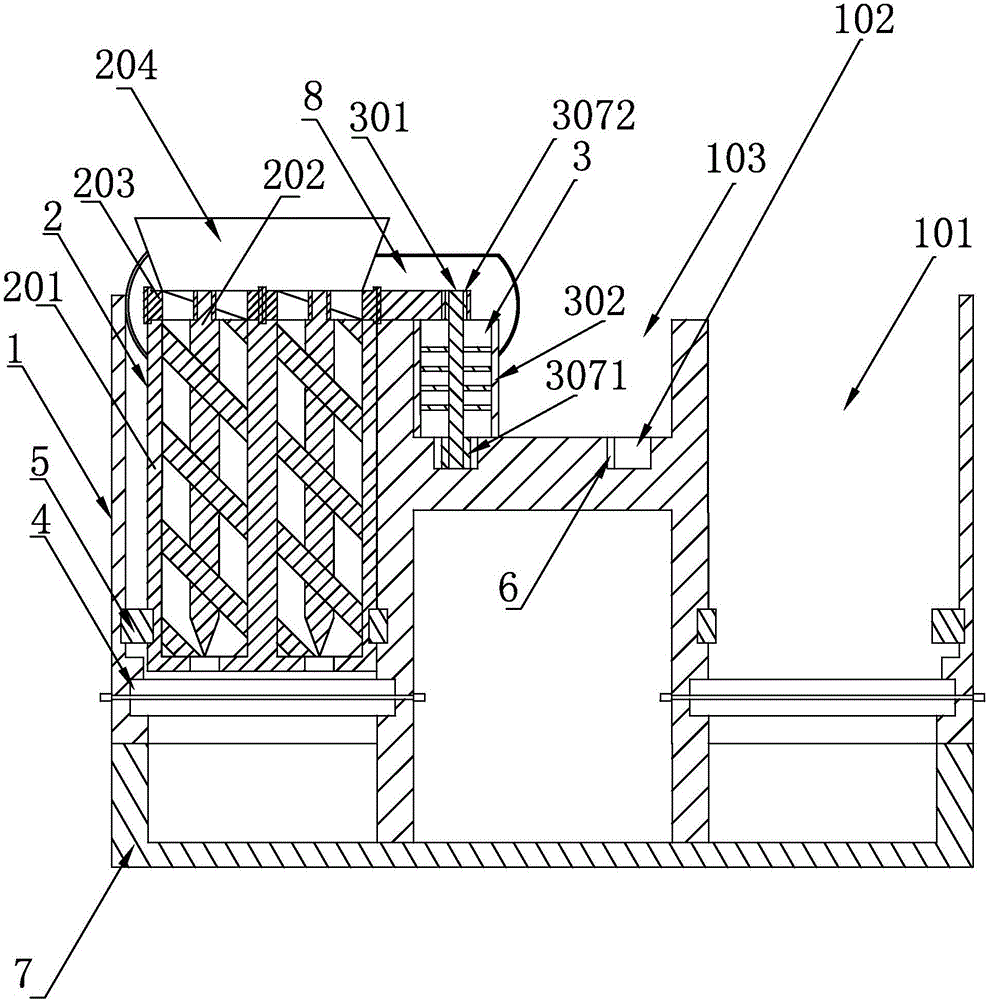
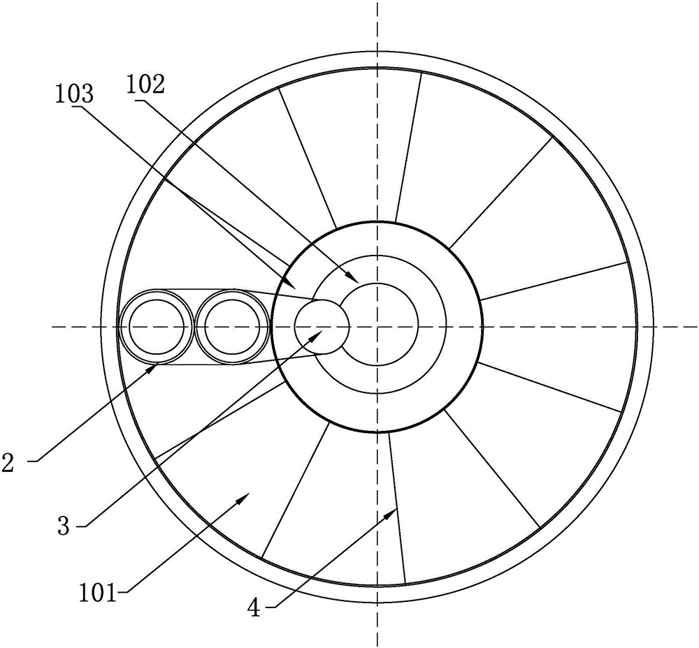
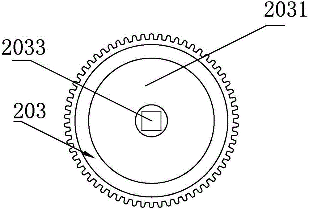
[0022] Such as figure 1 , figure 2 , image 3 , Figure 4 as well as Figure 5 As shown in , the present invention is a feeding type pneumatic food slicer, which includes a body 1, a rotating feeding mechanism 2, a pneumatic motor 3, and a material seat 7 placed at the bottom of the body 1, and the body 1 is provided with a first annular Groove 101, the pneumatic motor 3 is rotated and fitted on the body 1 and drives the rotary feeding mechanism 2 to rotate and fit in the first annular groove 101 so that the rotary feeding mechanism 2 is discharged downwards, and the rotating feeding mechanism 2 in the body 1 There is also a slicing mechanism 4 for cutting the material sent out by the rotary feeding mechanism 2 under the bottom; the first annular groove 101 communicates with the material cavity of the material seat 7 up and down.

[0023] The rotary fee...


PUM


Abstract

The invention discloses a feeding type pneumatic food slicing machine comprising a machine body (1), a rotary feeding mechanism (2) and a pneumatic machine (3). A first annular groove (101) is formed in the machine body (1); the pneumatic machine (3) rotates to match with the machine body (1) and drives the rotary feeding mechanism (2) to match with the first annular groove (101), so the rotary feeding mechanism (2) can downwardly feed; in the machine body (1), under the rotary feeding mechanism (2) is provided a slicing mechanism (4) cutting material discharged by the rotary feeding mechanism (2). The feeding type pneumatic food slicing machine is advantaged by low cost, high slicing efficiency and stable operation.

Description

technical field [0001] The invention relates to a feeding type pneumatic food slicer. Background technique [0002] The structure of the existing food slicing machine includes a horizontal feeding device and a cutting tool placed on the side of the discharge port of the feeding device. The cutter slices the material. Two power sources are required to realize the above process. One power source is responsible for conveying the material, that is, the material is continuously conveyed through the outlet of the feeding device; the other power source is responsible for slicing, that is, driving the cutting tool back and forth The movement realizes the slicing process of the material, which causes the above-mentioned food slicer to have shortcomings: due to the need to configure two power sources, on the one hand, the input cost is relatively large, and the cost of the subsequent operation of the entire food slicer is relatively high; On the one hand, if the power parameters of t...

Claims


Application Information

Patent Timeline
IPC IPC(8): B26D1/03B26D7/06
CPCB26D1/03B26D7/0608B26D2210/02
Inventor 陆昱森
Owner NINGBO CITY YINZHOU FENGMING IND PROD DESIGN
Learn More