A High Energy Efficiency and High Precision Quadrature Divider by Two

A technology of frequency divider and inverter, which is applied in automatic control of power and electrical components, etc. It can solve the problems of large power consumption, increase of parasitic capacitance, inaccurate layout area of ​​resistive load, etc., and achieves a simple and compact structure , the effect of high-speed conversion

Active Publication Date: 2018-11-02
UNIV OF SCI & TECH OF CHINA
View PDF3 Cites 0 Cited by
  • Summary
  • Abstract
  • Description
  • Claims
  • Application Information

AI Technical Summary

Problems solved by technology

This structure is formed by cascading two identical SCL flip-flops, the conversion speed is fast, but its power consumption is large; the tail current source in the SCL flip-flop is to ensure a relatively stable DC bias of the circuit, but the limitation If the tail current source is directly removed, it will increase the dependence of the circuit on the process and temperature; in addition, the resistive load of the SCL flip-flop has the disadvantages of inaccuracy and large layout area, although it can be considered to use active Load instead, but this will increase the parasitic capacitance, thereby limiting the maximum operating frequency of the structure of the quadrature divider by two

Method used


Image

  • A High Energy Efficiency and High Precision Quadrature Divider by Two
  • A High Energy Efficiency and High Precision Quadrature Divider by Two
  • A High Energy Efficiency and High Precision Quadrature Divider by Two

Examples


Embodiment Construction

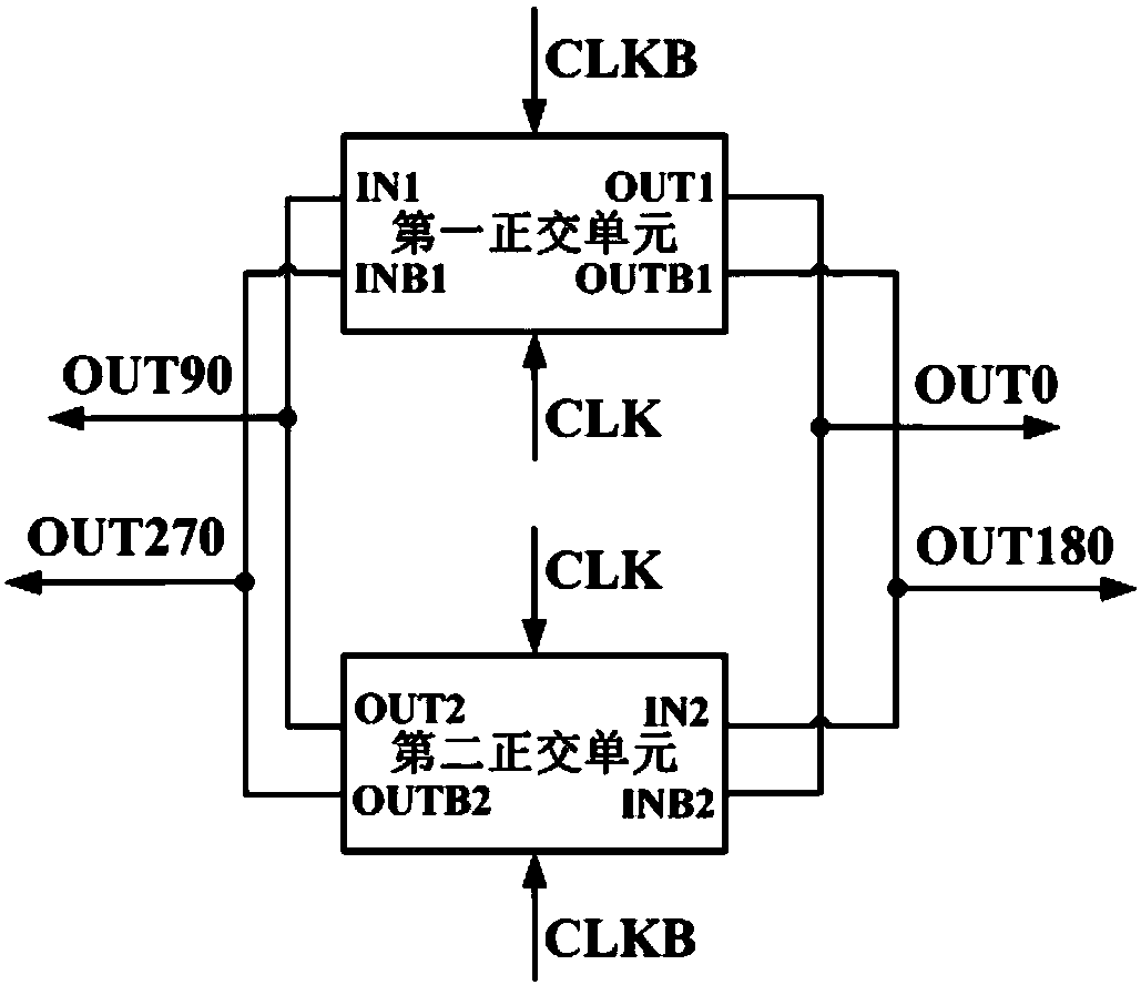
[0017] see figure 1 In this embodiment, the high-energy-efficiency and high-precision quadrature divider is formed by connecting the first quadrature unit and the second quadrature unit into a loop; the loop refers to the positive output terminal OUT1 and the negative output terminal of the first quadrature unit OUTB1 is respectively connected to the negative input terminal INB2 and the positive input terminal IN2 of the second orthogonal unit in one-to-one correspondence, and the positive output terminal OUT2 and the negative output terminal OUTB2 of the second orthogonal unit are connected to the first orthogonal unit in one-to-one correspondence. Positive input terminal IN1 and negative input terminal INB1.

[0018] In this embodiment, the first quadrature unit and the second quadrature unit are controlled by the differential input clock signals CLK and CLKB at the same time, the connection mode of the differential input clock signals CLK and CLKB in the first quadrature u...


PUM


Abstract

The invention discloses a high-energy-efficiency and high-precision orthogonal two-frequency divider. The orthogonal two-frequency divider is characterized that a first orthogonal unit and a second orthogonal unit are connected to form a loop. The first orthogonal unit and the second orthogonal unit are simultaneously controlled by differential input clock signals. The connection modes and control time sequences of the differential input clock signals in the first orthogonal unit and the second orthogonal unit are opposite to each other. Orthogonal two-frequency division signals are obtained at the positive output end OUT1 and negative output end OUTB1 of the first orthogonal unit, and the positive output end OUT2 and the negative OUTB2 of the second orthogonal unit. The orthogonal two-frequency divider is based on a digital circuit structure; no passive device and tail current source are employed; high-speed conversion can be obtained under a low power source voltage in high energy efficiency; and the orthogonal two-frequency divider has the advantages of technological flexibility and portability.

Description

technical field [0001] The invention relates to the technical field of digital and radio frequency integrated circuits, in particular to an orthogonal frequency divider by two. Background technique [0002] The frequency divider (Frequency Divider, FD) is widely used, for example, in the phase-locked loop (PLL) loop, it is used to divide the output signal of the voltage-controlled oscillator (VCO) to make it equal to the reference frequency, so as to achieve loop locking; It is used in the wireless transceiver to generate accurate quadrature carrier signals and perform quadrature modulation and demodulation on the signals. [0003] Traditional quadrature frequency dividers based on source-coupled logic (SCL) structures such as Figure 5 shown. This structure is formed by cascading two identical SCL flip-flops, the conversion speed is fast, but its power consumption is large; the tail current source in the SCL flip-flop is to ensure a relatively stable DC bias of the circuit...

Claims


Application Information

Patent Timeline
Patent Type & Authority Patents(China)
IPC IPC(8): H03L7/099
CPCH03L7/0992H03L2207/50
Inventor 黄森林福江
Owner UNIV OF SCI & TECH OF CHINA
Why Eureka
Try Eureka