
Micro-grid type solar charging pile and charging method

A technology of solar panels and charging piles is applied in AC network circuits, battery circuit devices, charging of different batteries, etc. It can solve the problems of short lifespan of system devices, low feasibility, and complicated methods, so as to improve the service life, Simple energy management structure and high power generation efficiency

Active Publication Date: 2016-12-07
SHANGHAI UNIV OF ENG SCI
View PDF5 Cites 0 Cited by
  • Summary
  • Abstract
  • Description
  • Claims
  • Application Information

AI Technical Summary

Problems solved by technology

However, this structure has the problem of short life and high cost of the system device because the battery is always in the state of charging and discharging.
At the same time, the energy relationship between input and output is judged by detecting the energy state of solar panels and batteries. The method is relatively complicated and not feasible.

Method used


Image

  • Micro-grid type solar charging pile and charging method
  • Micro-grid type solar charging pile and charging method
  • Micro-grid type solar charging pile and charging method

Examples


Embodiment

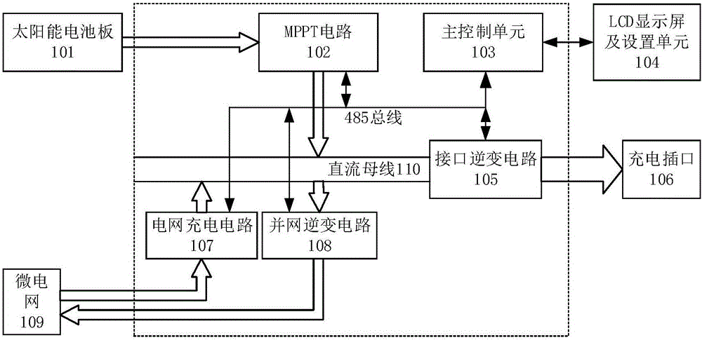
[0035] Such as figure 1 As shown, a micro-grid solar charging pile includes a solar panel 101, an MPPT circuit 102, a main control unit 103, an interface inverter circuit 105, a grid charging circuit 107, a grid-connected inverter circuit 108, and a micro-grid 109. The battery board 101 supplies power to the DC bus 110 through the MPPT circuit 102, the DC bus 110 is connected to the charging socket 106 through the interface inverter circuit 105, the DC bus 110 is also connected to the microgrid 109 through the grid-connected inverter 108, and the microgrid 109 is also connected to the microgrid 109 through the The grid charging circuit 107 is connected to the DC bus 110, and the main control unit 103 is respectively connected to the MPPT circuit 102, the interface inverter circuit 105, the grid charging circuit 107 and the grid inverter circuit 108. When the charging pile circuit is connected, the MPPT circuit 102 continuously transmits the energy flow collected by the solar p...


PUM


Abstract

The invention relates to a micro-grid type solar charging pile and a charging method. The charging pile comprises a solar panel (101), an MPPT (Maximum Power Point Tracking) circuit (102), a main control unit (103), an interface inverter circuit (105), a power grid charging circuit (107), a grid-connected inverter circuit (108) and a micro-grid (109), wherein the solar panel (101) supplies the power to a DC bus (110) through the MPPT circuit (102); the DC bus (110) is connected to a charging socket (106) through the interface inverter circuit (105); the DC bus (110) is also connected to the micro-grid (109) through the grid-connected inverter circuit (108); the micro-grid (109) is also connected to the DC bus (110) through the power grid charging circuit (107); the main control unit (103) is respectively connected to the MPPT circuit (102), the interface inverter circuit (105), the power grid charging circuit (107) and the grid-connected inverter circuit (108) through signals. In comparison with the prior art, the micro-grid type solar charging pile and the charging method have the advantages that an energy management structure is simple and low in cost and the charging pile has good stability.

Description

technical field [0001] The invention relates to a charging pile, in particular to a micro-grid solar charging pile and a charging method. Background technique [0002] New energy electric vehicles are an inevitable trend in the future of the automobile industry. Solving the charging problem of electric vehicles can promote the rapid promotion of new energy vehicles. Just like fuel vehicles cannot do without gas stations, electric vehicles cannot do without charging piles. Using solar energy as the energy source for charging piles is also the direction of future charging pile design. It is urgent to design a micro-grid solar charging pile. up. However, due to the influence of unstable solar power generation efficiency, the problem of insufficient solar power supply or excess solar power supply will be encountered during the charging process. How to reasonably realize the scheduling between the power grid and photovoltaic energy while ensuring the stability of the output volt...

Claims


Application Information

Patent Timeline
Patent Type & Authority Applications(China)
IPC IPC(8): H02J7/00H02J1/10H02J3/38
CPCH02J1/102H02J3/385H02J7/0047Y02E10/56
Inventor 郑树彬彭乐乐柴晓冬张雯柏王玉玲
Owner SHANGHAI UNIV OF ENG SCI
Learn More