Heat dissipation structure for connector module

A technology of connector module and heat dissipation structure, which is applied in the direction of connection, provision of connectors and printed circuit boards, installation of connection components, etc., can solve the problems of short circuit of control board, increase of heat, easy damage of control board, etc., and improve heat dissipation performance , the effect of reducing the possibility of damage and short circuit

Active Publication Date: 2016-12-07
YAZAKI CORP
View PDF19 Cites 3 Cited by
  • Summary
  • Abstract
  • Description
  • Claims
  • Application Information

AI Technical Summary

Problems solved by technology

[0004] However, in the heat dissipation structure described in Patent Document 1, heat is released from a metal case having such a size as to accommodate the control board
Thus, if the generated heat becomes large as in the case where the module is arranged on a path through which a large current flows, the heat dissipation performance is insufficient, and thus it is necessary to improve the heat dissipation performance
Furthermore, in the heat dissipation structure described in Patent Document 1, since the control board is assembled in the metal case in a sliding manner, the control board is easily damaged
In addition, since the control board is directly attached to the metal case, there is a high possibility of shorting the control board

Method used


Image

  • Heat dissipation structure for connector module
  • Heat dissipation structure for connector module
  • Heat dissipation structure for connector module

Examples


Embodiment Construction

[0098] Exemplary embodiments are described below with reference to the accompanying drawings.

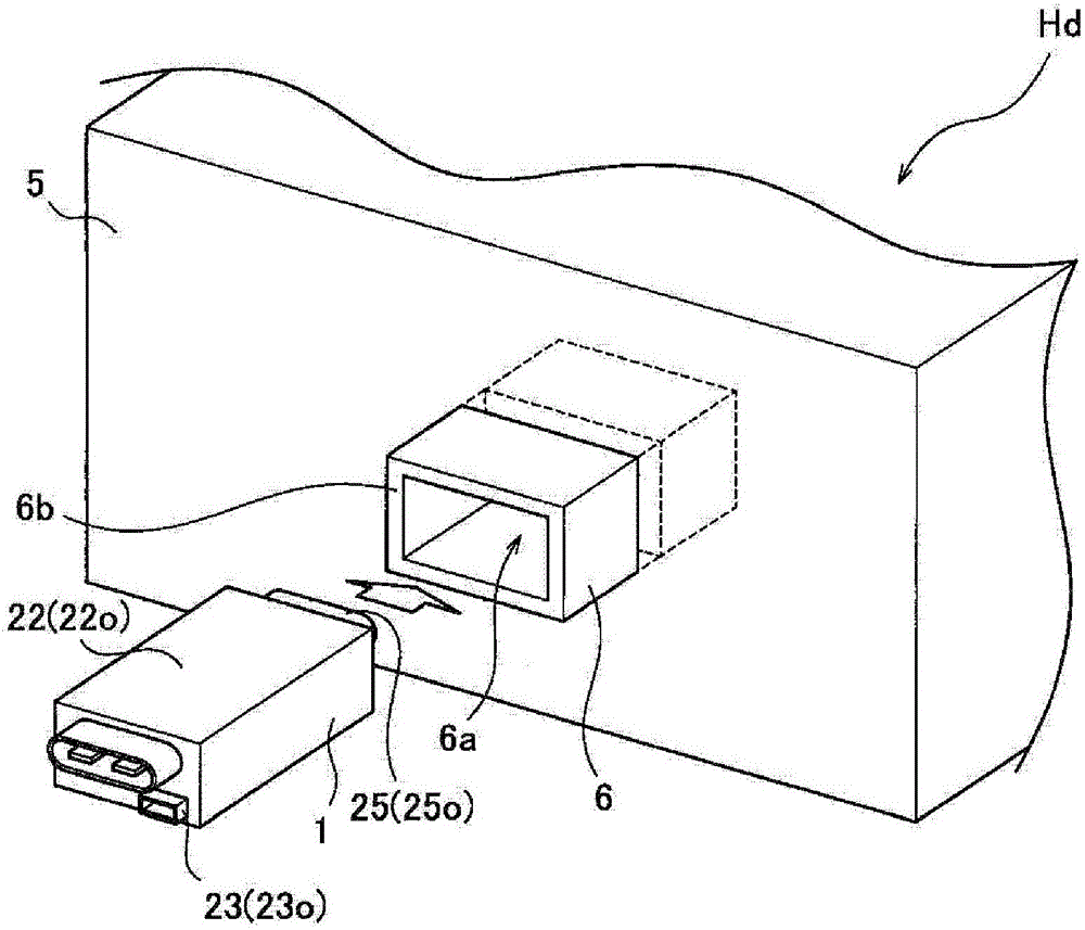
[0099] figure 1 is a perspective view showing the heat dissipation structure for the connector module according to the first embodiment of the present invention. Such as figure 1 As shown, the heat dissipation structure Hd for the connector module 1 is composed of the connector module 1 and the metal case (metal part) 5 . The connector block 1 is provided, for example, on a path through which a large current flows, and contains a heat generating element (see reference numeral 11c described later). The metal case 5 is, for example, a battery case for a high-voltage battery installed in a vehicle.

[0100] A module fixing portion 6 into which the connector module 1 is inserted and fixed is formed in this metal case 5 . Such as figure 1 As shown, the module fixing portion 6 is composed of a rectangular opening 6a and a frame member 6b. The frame member vertically extends from one...


PUM


Abstract

A connector module is provided with first and second bus bars which are respectively formed by a metal plate, a control board on which an electronic component is mounted, and case member which is formed by insulative resin and houses the control board therein. Connector parts to be connected with respective counterpart connectors are integrally formed with the case member.

Description

technical field [0001] The invention relates to a heat dissipation structure for a connector module. Background technique [0002] In a module including a control board on which connectors and electronic components are mounted and a metal case accommodating the control board in a sliding manner, there has been proposed a heat dissipation structure provided with a protrusion protruding inside the metal case to near electronic components. In this heat dissipation structure, since the heat generated from the electronic component can be released to the ambient air through the protrusion of the metal case, the heat dissipation performance can be improved (see Patent Document 1: JP-A-2011-198985). [0003] [Patent Document 1] JP-A-2011-198985 [0004] However, in the heat dissipation structure described in Patent Document 1, heat is released from the metal case having such a size as to accommodate the control board. Thus, if like in the case where the module is arranged on a pa...

Claims


Application Information

Patent Timeline
IPC IPC(8): H01L23/367H05K7/20
CPCH01L23/367H05K7/20H01R13/74H01R31/065B60L2240/36Y02T10/7072Y02T90/14H01L2224/4903B60L53/16Y02T10/70H05K5/0026
Inventor 森本充晃大石英一郎
Owner YAZAKI CORP
Why Eureka
Try Eureka