
an optical system

A technology of optical system and projection optical system, which is applied in the direction of optics, optical components, instruments, etc., can solve the problems of small focus range, low resolution, and low resolution, and achieve the same definition, clear projection picture, high resolution effects

Active Publication Date: 2018-08-03
UNION OPTECH
View PDF6 Cites 0 Cited by
  • Summary
  • Abstract
  • Description
  • Claims
  • Application Information

AI Technical Summary

Problems solved by technology

[0002] At present, the zoom projection optical system used in projectors generally has such shortcomings: the resolution is low, and synchronous zooming cannot be realized during the zooming process, that is, the lens needs to adjust the focus group to make the picture clear during the zooming process, and the focus range is small. , high temperature virtual focus, large volume, small magnification, etc.
At present, there is no lens on the market that can overcome the above shortcomings at the same time. There are only a few lenses that can only be improved in one aspect, but at the expense of other performance indicators of the lens. For example, in order to achieve synchronous zoom, the volume of the projection optical system must be increased; in order to achieve A shorter focusing distance will complicate the projection optical system; for high temperature confocal, glass lenses must be used, resulting in lower resolution; in order to increase the projection magnification, the brightness of the projection screen must be reduced, etc. These far It cannot meet the requirements of the projection lens on the market for projection clarity, miniaturization, no need to focus during zooming, and high temperature without virtual focus. Currently, there is no zoom projection lens on the market that overcomes all the above shortcomings.

Method used


Image

  • an optical system
  • an optical system
  • an optical system

Examples


Embodiment Construction

[0019] The present invention will be further described below in conjunction with accompanying drawing:

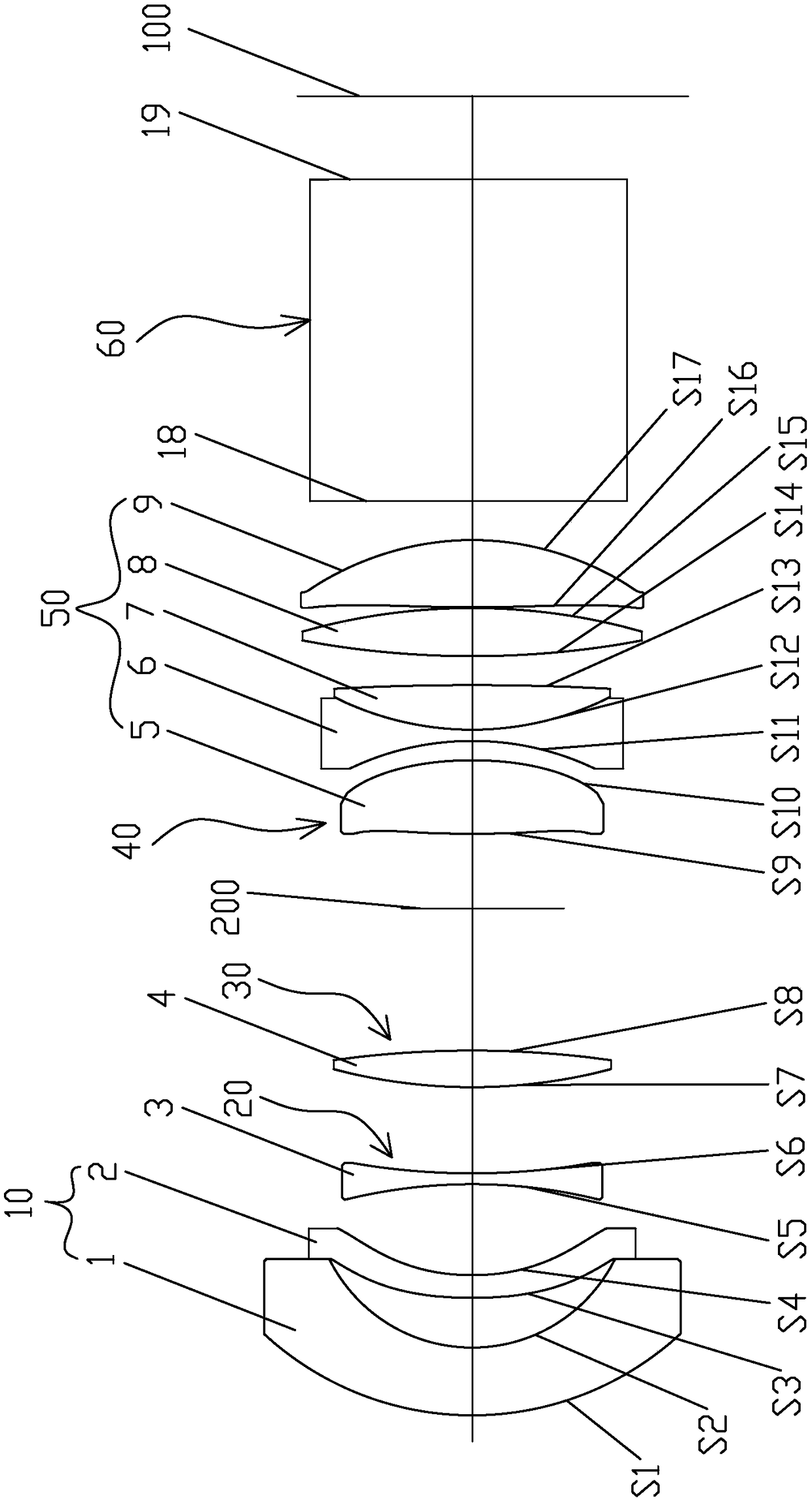
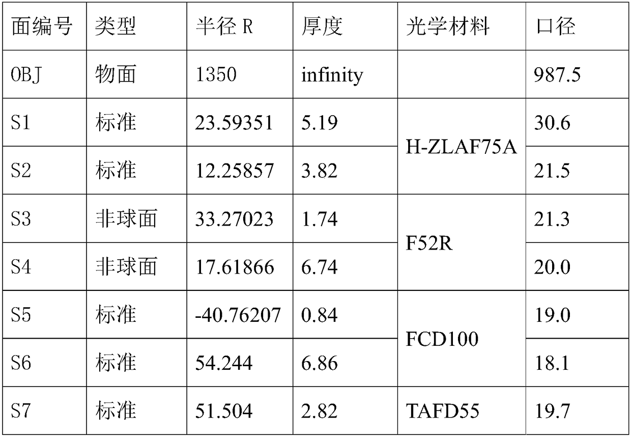
[0020] An optical system, comprising a light-emitting chip 100, one side of the light-emitting chip 100 is provided with a first lens group 10 fixed relative to it, and a lens capable of opposing the light-emitting chip is arranged between the first lens group 10 and the light-emitting chip 100. 100 moves to complete the second lens group 20 of the projection optical system focusing, and the third lens that can move relative to the light-emitting chip 100 at the same time is arranged between the second lens group 20 and the light-emitting chip 100 to complete the variable magnification of the projection optical system group 30, diaphragm 200, fourth lens group 40 and fifth lens group 50, wherein the refractive power φ of the first lens group 10 1 is negative, the optical power φ of the second lens group 20 2 is negative, the optical power φ of the third lens group 30 3 is...


PUM


Abstract

The invention discloses an optical system, and the system comprises a light-emitting chip. One side of the light-emitting chip is provided with a first lens group which is fixed relative to the light-emitting chip. A second lens group which can move relative to the light-emitting chip and completes the focusing of a projection optical system is disposed between the first lens group and the light-emitting chip. A third lens group which can move relative to the light-emitting chip at the same time and completes the zooming of the projection optical system, a diaphragm, a fourth lens group and a fifth lens group are disposed between the second lens group and the light-emitting chip. A prism is disposed between the fifth lens group and the light-emitting chip. The focal power Phi1 of the first lens group is negative, and the focal power Phi2 of the second lens group is negative. The focal power Phi3 of the third lens group is positive, the focal power Phi4 of the fourth lens group is positive, and the focal power Phi5 of the fifth lens group is positive. The optical system is simple in structure, is large in aperture, is small in size, is high in number of pixels, and can achieve the synchronous zooming, micro-focusing, high-temperature co-focusing, and high-pixel zooming.

Description

【Technical field】 [0001] The invention relates to an optical system. 【Background technique】 [0002] At present, the zoom projection optical system used in projectors generally has such shortcomings: the resolution is low, and synchronous zooming cannot be realized during the zooming process, that is, the lens needs to adjust the focus group to make the picture clear during the zooming process, and the focus range is small. , high temperature virtual focus, large volume, small magnification and so on. At present, there is no lens on the market that can overcome the above shortcomings at the same time. There are only a few lenses that can only be improved in one aspect, but at the expense of other performance indicators of the lens. For example, in order to achieve synchronous zoom, the volume of the projection optical system must be increased; in order to achieve A shorter focusing distance will complicate the projection optical system; for high temperature confocal, glass ...

Claims


Application Information

Patent Timeline
Patent Type & Authority Patents(China)
IPC IPC(8): G02B15/177G03B21/14
CPCG02B15/177G03B21/142
Inventor 全丽伟李建华王晓贾丽娜朱洪婷龚俊强
Owner UNION OPTECH
Learn More