
Oil-air separator and air-conditioning system with same

A technology of oil and gas separator and oil filter, applied in compressors, refrigeration components, refrigerators, etc., can solve the problems of affecting the heat exchange efficiency of heat exchangers, reducing the energy efficiency of units, and increasing the exhaust resistance of compressors. The principle of oil separation is simple and reliable, the effect of improving oil separation effect and reducing separation resistance

Inactive Publication Date: 2016-12-07
CHONGQING MIDEA GENERAL REFRIGERATING EQUIP +1
View PDF7 Cites 2 Cited by
  • Summary
  • Abstract
  • Description
  • Claims
  • Application Information

AI Technical Summary

Problems solved by technology

[0002] With the increasing demand for environmentally friendly air conditioners, high efficiency and energy saving have become a new direction for the development of screw chiller technology, and the oil return problem in screw chillers is a key factor affecting the efficiency of the unit, because the oil return is not timely, It will cause a large amount of oil in the system, affect the heat exchange efficiency of the heat exchanger, increase the wear of the compressor, and reduce the superheat of the suction air. The quality of the oil return is determined by the oil-gas separator.
The oil and gas separation of the existing oil and gas separator often has a large pressure loss, resulting in an increase in the exhaust resistance of the compressor and a corresponding decrease in the energy efficiency of the unit

Method used


Image

  • Oil-air separator and air-conditioning system with same
  • Oil-air separator and air-conditioning system with same

Examples


Embodiment Construction

[0022] Embodiments of the invention are described in detail below, examples of which are illustrated in the accompanying drawings. The embodiments described below by referring to the figures are exemplary and are intended to explain the present invention and should not be construed as limiting the present invention.

[0023] In the description of the present invention, it should be understood that the orientations or positional relationships indicated by the terms "upper", "lower", "left", "right", "bottom", "outer" etc. are based on those shown in the accompanying drawings. Orientation or positional relationship is only for the convenience of describing the present invention and simplifying the description, and does not indicate or imply that the referred device or element must have a specific orientation, be constructed and operated in a specific orientation, and thus should not be construed as a limitation of the present invention.

[0024] In the present invention, unless ...


PUM


Abstract

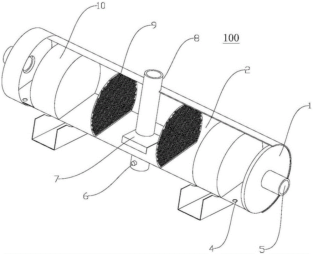
The invention discloses an oil-air separator and an air-conditioning system with the same. The oil-air separator comprises a housing, an oil baffle plate, an air inlet pipe, at least one air homogenizing plate, and an oil filter assembly, wherein the housing comprises an upper chamber and a lower chamber; an oil drain outlet communicating with the lower chamber is formed in a bottom wall of the upper chamber, and an air outlet is formed in the upper chamber, while a collected oil outlet is formed in the lower chamber; the oil baffle plate is disposed on the bottom wall of the upper chamber; one end of the air inlet pipe extends into the upper chamber and is located above the oil baffle plate, and a gap is formed between a bottom end of the air inlet pipe and the oil baffle plate to define a circulation passage; each air homogenizing plate is disposed in the upper chamber, and a plurality of air vents are formed in each air homogenizing plate; the oil filter assembly is disposed in the upper chamber; and in an air circulation direction, each air homogenizing plate is located downstream of the circulation passage, and the oil filter assembly is located downstream of the air homogenizing plate. The oil-air separator provided by the present invention is capable of improving the oil separation effect, and is simple in structure, and simple and reliable in oil separation principle.

Description

technical field [0001] The invention relates to the field of refrigeration, in particular to an oil-gas separator and an air-conditioning system with the same. Background technique [0002] With the increasing demand for environmentally friendly air conditioners, high efficiency and energy saving have become a new direction for the development of screw chiller technology, and the oil return problem in screw chillers is a key factor affecting the efficiency of the unit, because the oil return is not timely, It will cause a large amount of oil to accumulate in the system, affect the heat exchange efficiency of the heat exchanger, increase the wear of the compressor, and reduce the superheat of the suction air. The quality of the oil return is determined by the oil-gas separator. The oil-gas separation of the existing oil-gas separator often has a large pressure loss, resulting in an increase in the exhaust resistance of the compressor and a corresponding decrease in the energy...

Claims


Application Information

Patent Timeline
Patent Type & Authority Applications(China)
IPC IPC(8): F25B43/02F25B31/00
CPCF25B43/02F25B31/004
Inventor 顾同先
Owner CHONGQING MIDEA GENERAL REFRIGERATING EQUIP
Learn More