
Industrial tail gas liquefaction energy storage power generation system and power generation method

A technology for industrial tail gas and power generation systems, applied in liquefaction, refrigeration and liquefaction, machines/engines, etc., can solve the problems of exhaust resource waste, environmental pollution, high cost, etc., and achieve resource saving, safety improvement, high efficiency, energy saving and emission reduction The effect of environmental protection

Active Publication Date: 2016-12-07
成都聚熵能源科技有限公司
View PDF7 Cites 4 Cited by
  • Summary
  • Abstract
  • Description
  • Claims
  • Application Information

AI Technical Summary

Problems solved by technology

[0003] The technical problem to be solved by the present invention is the comprehensive recovery and reuse of industrial tail gas, providing an industrial tail gas liquefaction energy storage power generation system and power generation method, and solving the current environmental pollution caused by the discharge of industrial coal, fuel oil and gas tail gas into the atmosphere , and the high cost problems caused by the construction of energy storage power stations or peak shaving power stations, and the waste of resources caused by the failure to comprehensively recover and reuse exhaust gas

Method used


Image

  • Industrial tail gas liquefaction energy storage power generation system and power generation method
  • Industrial tail gas liquefaction energy storage power generation system and power generation method

Examples


Embodiment 1

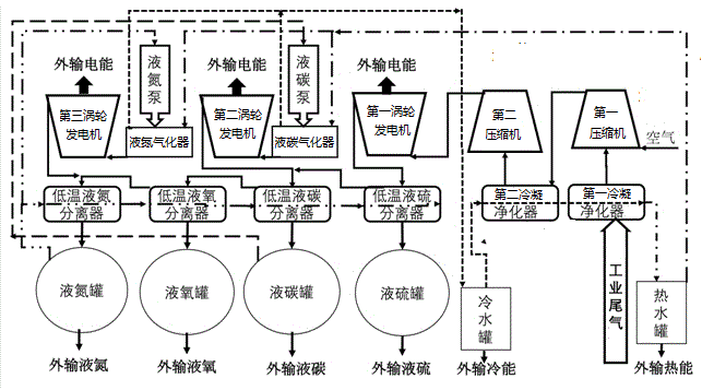
[0048] Such as figure 1 As shown, figure 1 It is a structural block diagram of the industrial exhaust gas liquefaction energy storage system provided in Embodiment 1 of the present invention.

[0049] In this embodiment, an industrial tail gas liquefaction energy storage power generation system includes a tail gas purification heat storage unit, a tail gas turbine power generation unit, a liquefaction separation storage unit, and a supercharged gasification power generation unit.

[0050] The exhaust gas purification and heat storage unit includes a hot water tank, a cold water tank, a first condensation purifier, a second condensation purifier, a first compressor, and a second compressor. The industrial exhaust gas enters the first condensation purifier to perform processing on the industrial exhaust gas. The first condensing purification treatment such as cooling, water vapor condensation and solid-phase soot precipitation, the first compressor pressurizes the industrial exhaust g...

Embodiment 2

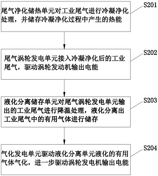
[0058] Such as figure 2 As shown, figure 2 It is a flow chart of the method for power generation by liquefaction of industrial tail gas provided in Embodiment 2 of the present invention.

[0059] In this embodiment, the method for power generation using the industrial tail gas liquefaction energy storage power generation system described in the first embodiment includes the following steps:

[0060] S201. The exhaust gas purification heat storage unit condenses and purifies the industrial exhaust gas, and stores the heat energy generated in the condensation purification process.

[0061] The first condenser performs the first condensation purification treatment of the incoming industrial exhaust gas, such as cooling, water vapor condensation and solid-phase soot deposition. The first compressor mixes and pressurizes the industrial exhaust gas and air after the first condensation purification treatment. The second condensing processor performs the second condensation purification ...


PUM


Abstract

The invention discloses an industrial tail gas liquefaction energy storage power generation system and a power generation method. The system is characterized in that industrial tail gas is subjected to condensation and purification through a tail gas purification heat storage unit; heat energy generated during the condensation and purification process is stored; electric energy is generated from condensed and purified tail gas through a tail gas turbine power generation unit; useful gases like sulfur, carbon, oxygen and nitrogen are liquefied and separated from tail gas output by the tail gas turbine power generation unit through a liquefaction separation storage unit; a pressurization gasification power generation unit drives liquefied useful gases of the liquefaction separation unit to be gasified, and electric energy is further generated; and thereby, industrial tail gas liquefaction, separation, storage and gasification power generation are achieved, the comprehensive utilization rate and emission reduction rate of industrial tail gas are increased, the energy compensation problem of peak regulating and valley filling is efficiently solved, investment of matching generating sets, power transmission and distribution facilities and gas supply networks for building energy storage power stations or peak regulating power stations is reduced, the remote power supply loss and running cost are reduced, and the safety, stability and economy of power supply and peak regulating are improved.

Description

Technical field [0001] The invention relates to the technical field of energy and environmental protection, in particular to an industrial tail gas liquefaction energy storage power generation system and a power generation method. Background technique [0002] At present, although the exhaust gas discharged from industrial coal, oil, gas and other energy power generation has undergone conventional purification treatments such as dust removal, desulfurization, and destocking, the pollutant unit concentration will be discharged to the atmosphere after reaching the standard. Energy saving and environmental protection have been initially realized. However, the actual industrial exhaust gas There are also the following problems in the emission process: 1. Environmental protection and emission reduction. Although the unit concentration of pollutants in the discharged industrial tail gas meets the standard, it has not fundamentally solved the environmental protection and emission reduct...

Claims


Application Information

Patent Timeline
Patent Type & Authority Applications(China)
IPC IPC(8): F01K25/14F01K25/10F25B27/02F25J3/00
CPCF25J1/0251F25J1/0015F25J1/0017F25J1/0027F25J1/0035F25J1/0045F25J1/0242F25J2210/70F25J2230/30F01K25/14F01K25/10F25B27/02F25J3/066F25J2215/04F25J2215/42F25J2215/50
Inventor 牛辉英付万春付睿
Owner 成都聚熵能源科技有限公司
Learn More