Continuous beam structure provided with V-shaped webs and construction method of continuous beam structure

A continuous web and beam structure technology, applied to bridges, bridge construction, bridge parts, etc., can solve the problems of bridge structure stiffness and strength reduction, long construction period, and accelerated steel corrosion, so as to improve the durability index and put into construction Low cost and the effect of reducing project cost

Inactive Publication Date: 2016-12-07
XIAN HIGHWAY INST
View PDF8 Cites 2 Cited by
  • Summary
  • Abstract
  • Description
  • Claims
  • Application Information

AI Technical Summary

Problems solved by technology

Years of engineering practice has reflected that there are many structural problems in prestressed concrete box girder bridges, which are mainly reflected in the following three aspects: First, self-heaviness: the structural self-weight accounts for 80% to 90% of the total internal force in the design value of the internal force of the control section. %, the larger the span, the larger the ratio, which greatly restricts the spanning capacity of the bridge. At the same time, due to the limitation of hoisting capacity, the hoisting tonnage should not be too large, so the span of prestressed concrete box girder bridges is generally not If it is too large, the problems brought about by this are: the number of foundations increases, which in turn leads to a series of problems such as a large impact on water flow, many times of beam erection, and a long construction period; second, due to the low tensile strength of conventional concrete, in order to Large-span bridges usually increase the section size and plate thickness to increase the section stiffness to meet the structural force requirements, which not only increases the weight of the box girder and the project cost, but also increases the difficulty of construction ; Third, the concrete web of the box girder is easy to crack, which affects the mechanical performance and durability of the bridge
Due to the complexity of the force and some reasons in the structural treatment and construction of the concrete web, most of the concrete webs will have oblique cracks. The reinforced steel will cause volume expansion, which will crack the concrete, further damage the mechanical performance of the concrete, reduce the durability of the material and the bearing capacity of the structure, and affect the beauty and service life of the bridge.
If the bridge adopts a steel structure or a steel-concrete composite structure, its span can indeed be greatly increased compared with the prestressed concrete continuous beam bridge, but due to the influence of the steel structure being easily corroded, its later maintenance costs are high
At the same time, the high cost of bridges with steel structures will lead to poor economic efficiency, which seriously hinders the engineering application of steel structures or steel-concrete composite structure bridges
[0003] At present, some long-span box girder bridges use high-performance lightweight aggregate concrete in the middle of the main span (such as the Stolma Bridge in Norway with a main span of 301m) and steel box girders in the middle of the main span (such as the 330m main span bridge). Chongqing Shibanpo Yangtze River Bridge double-track bridge) and other methods to improve its spanning capacity, and methods such as web vertical prestressed tendons to reduce the risk of box girder cracking. Although these methods have certain effects, the design and construction process of these schemes are relatively complicated At the same time, the problem of box girder cracking has not been fundamentally solved

Method used


Image

  • Continuous beam structure provided with V-shaped webs and construction method of continuous beam structure
  • Continuous beam structure provided with V-shaped webs and construction method of continuous beam structure
  • Continuous beam structure provided with V-shaped webs and construction method of continuous beam structure

Examples


Embodiment Construction

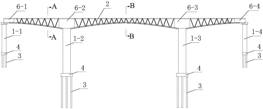
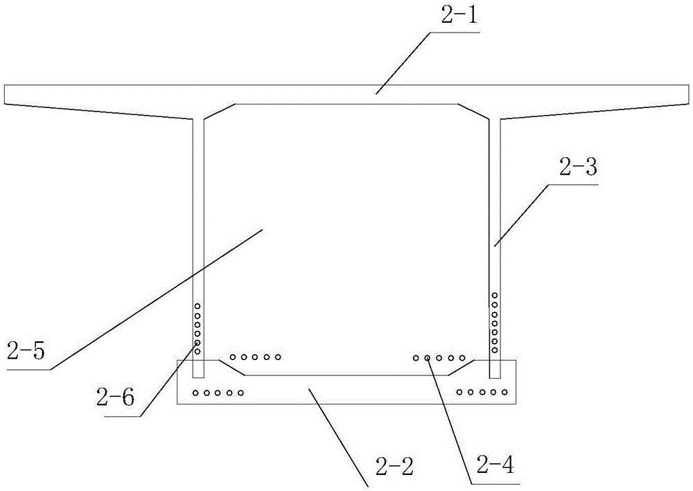
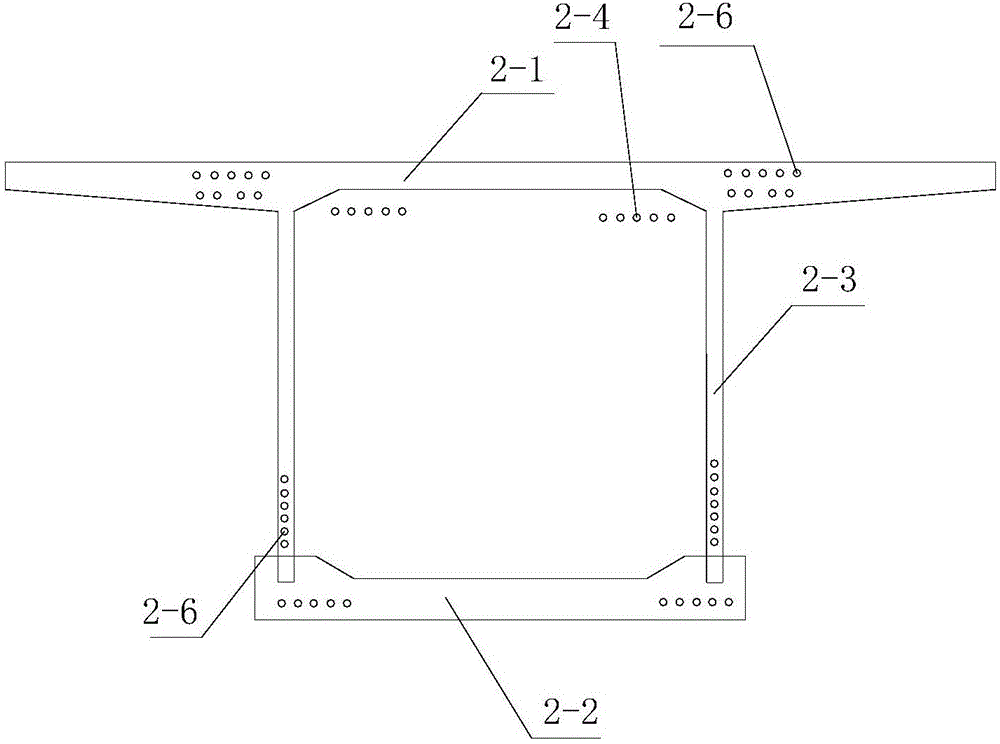
[0053] Such as figure 1 , figure 2 and image 3 A V-shaped web continuous girder structure shown includes a bridge lower support system and a composite box girder 2 erected on the bridge lower support system, and the composite box girder 2 includes a roof 2-1, a 1 bottom plate 2-2 and two left and right V-shaped webs 2-3 symmetrically connected between the top plate 2-1 and the bottom plate 2-2; the top plate 2-1 and the bottom plate 2-2 are made of high-strength concrete A poured concrete slab, the V-shaped web 2-3 is composed of a plurality of V-shaped prefabricated slabs arranged along the longitudinal bridge direction, and the plurality of V-shaped prefabricated slabs are arranged along the longitudinal bridge direction from front to back , the V-shaped prefabricated slab is a concrete prefabricated slab cast from ultra-high performance concrete.

[0054] In this embodiment, both the top plate 2-1 and the bottom plate 2-2 are cast-in-place concrete plates made of high-...


PUM


Abstract

The invention discloses a continuous beam structure provided with V-shaped webs and a construction method of the continuous beam structure. The continuous beam structure provided with the V-shaped webs comprises a bridge lower part support system and a combination box beam erected on the bridge lower part support system, wherein the combination box beam comprises a top plate, a bottom plate located below the top plate as well as a left V-shaped web and a right V-shaped web which are symmetrically connected between the top plate and the bottom plate; the top plate and the bottom plate are concrete slabs formed by casting UHPC (ultra-high performance concrete), each V-shaped web comprises a plurality of V-shaped precast slabs and is arranged in the longitudinal bridge direction, and the V-shaped precast slabs are V-shaped precast concrete slabs formed by casting UHPC. The construction method comprises the following steps: 1, constructing the bridge lower part support system and prefabricating the V-shaped precast slabs; 2, constructing the combination box beam. The continuous beam structure provided with the V-shaped webs and the construction method of the continuous beam structure have the advantages that the design is reasonable, the construction is simple and convenient, the using effect is good, the top plate and the bottom plate made of the UHPC are combined with the V-shaped webs made of the UHPC, and the stress performance and the durability of a bridge are improved effectively.

Description

technical field [0001] The invention belongs to the technical field of bridge construction, and in particular relates to a V-shaped web continuous beam structure and a construction method thereof. Background technique [0002] Conventional prestressed concrete continuous girder bridges and continuous rigid frame bridges are the most widely used bridge structure forms in my country's traffic engineering at present. Box girder structures are generally used, and the applicable spans range from 60m to 330m. Years of engineering practice has reflected that there are many structural problems in prestressed concrete box girder bridges, which are mainly reflected in the following three aspects: First, self-heaviness: the structural self-weight accounts for 80% to 90% of the total internal force in the design value of the internal force of the control section. %, the larger the span, the larger the ratio, which greatly restricts the spanning capacity of the bridge. At the same time, ...

Claims


Application Information

Patent Timeline
Patent Type & Authority Applications(China)
IPC IPC(8): E01D19/00E01D21/00
CPCE01D19/00E01D21/00
Inventor 袁卓亚李立峰崔文社石雄伟柯亮亮雷丹许冰马毓泉冯威李辉辉杨芳
Owner XIAN HIGHWAY INST
Why Eureka
Try Eureka