


Quick Research
Generate reliable direction feasibility study reports for your R&D in just a few steps.

Technical Q&A
Discover and master advanced knowledge NOW. Basics, ideas, possibilities, all at once.

Find Solutions
As an expert in R&D theories, this can generate solutions to your technical problems instantly.

Evaluate Feasibility
Analyze your overall solution with one click, know your potential R&D risks in advance.

Monitor Landscape
Get weekly tech updates, stay abreast of the latest tech innovations and key insights.
Parachute throwing device for unmanned aerial vehicle and unmanned aerial vehicle
A technology of unmanned aerial vehicles and paracords, applied in the field of unmanned aerial vehicles, can solve the problems of unpopularity, high price and high use cost for civilian use.
- Summary
- Abstract
- Description
- Claims
- Application Information
AI Technical Summary
Problems solved by technology
Method used
Image

Examples
Embodiment 1
[0028] The UAV parachute throwing device provided in this embodiment includes a paracord pin, a casing, a drive mechanism, a transmission mechanism and a clamping mechanism for clamping the paracord pin; The output shaft of the driving mechanism is connected with the transmission mechanism for driving the clamping mechanism to rotate, and the transmission mechanism is connected with the clamping mechanism for driving the clamping mechanism to release the paracord pin; The casing is provided with an opening so that the paracord pin can be disengaged from the clamping mechanism through the opening.
[0029] In the UAV parachute throwing device provided in this embodiment, when the parachute needs to be connected to the clamping mechanism, the parachute pin connected to the parachute is clamped in the casing by the clamping mechanism, thereby fixing the parachute on the parachute throwing device When the parachute needs to be thrown, the transmission mechanism is used to drive th...
Embodiment 2
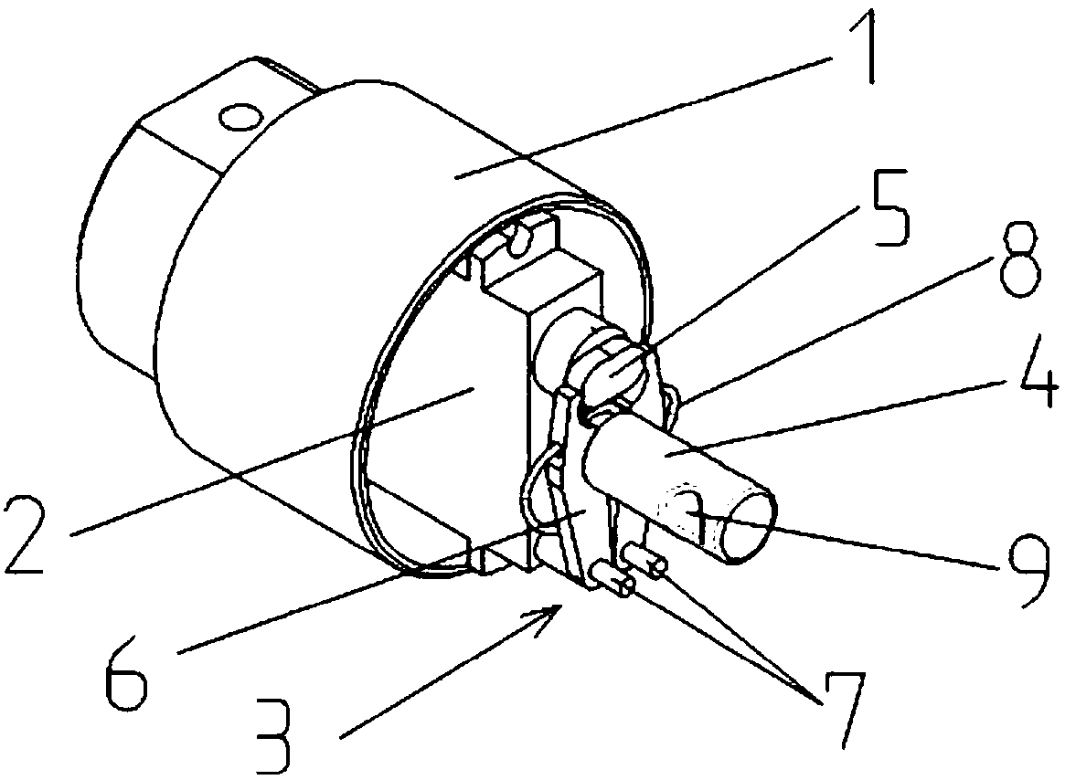
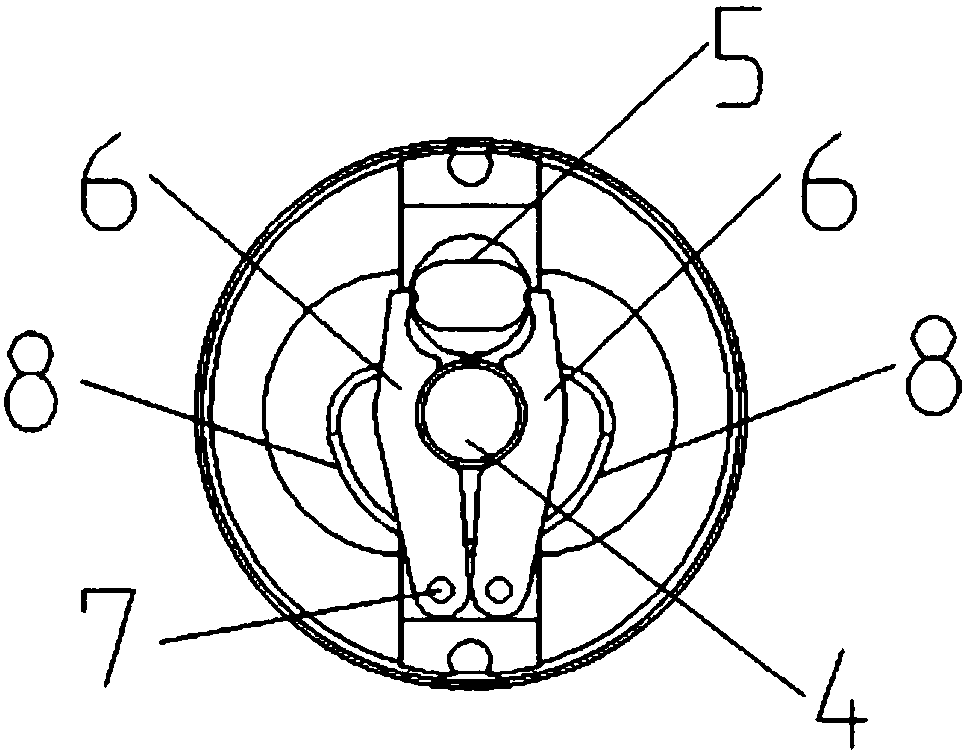
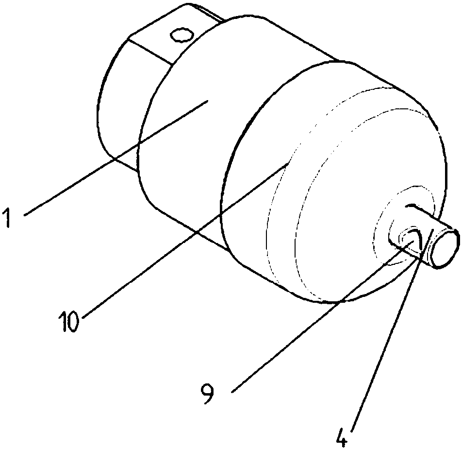
[0031] like Figures 1 to 4 As shown, the UAV parachute throwing device provided in this embodiment includes a paracord pin 4, a housing 1, a drive mechanism 2 arranged inside the housing 1, a transmission mechanism, and a drive mechanism for clamping the paracord The clamping mechanism 3 of the pin 4; the output shaft of the driving mechanism 2 is connected with the transmission mechanism for driving the clamping mechanism 3 to rotate, and the transmission mechanism is connected with the clamping mechanism 3 for driving The clamping mechanism 3 releases the paracord pin 4 ; the housing 1 is provided with an opening so that the paracord pin 4 can pass through the opening to be separated from the clamping mechanism 3 .
[0032] The driving mechanism 2 is preferably a servo steering gear, the transmission mechanism includes a cam 5, and the clamping mechanism 3 includes a caliper shaft 7, a circlip 8 and a caliper that rotates around the caliper shaft 7; the caliper includes two...
Embodiment 3
[0039] The UAV provided in this embodiment includes a body, a parachute, and the UAV parachute throwing device described in the above-mentioned first or second embodiment. Rope pin connection.
PUM
 Abstract
Description
Claims
Application Information
 - R&D Engineer
- R&D Manager
- IP Professional
- Industry Leading Data Capabilities
- Powerful AI technology
- Patent DNA Extraction
Browse by: Latest US Patents, China's latest patents, Technical Efficacy Thesaurus, Application Domain, Technology Topic, Popular Technical Reports.
© 2024 PatSnap. All rights reserved.Legal|Privacy policy|Modern Slavery Act Transparency Statement|Sitemap|About US| Contact US: help@patsnap.com