Simple internal bracing clamp for friction-stir welding circumferential weld

A technology of friction stir welding and internal support fixtures, which is applied in the direction of manufacturing tools, welding equipment, auxiliary welding equipment, etc., can solve the problems of high manufacturing cost, large force in the tangential direction, and high cost, so as to ensure welding quality and avoid welding Staggered stitching and short manufacturing cycle

Inactive Publication Date: 2016-12-07
SICHUAN AEROSPACE LONG MARCH EQUIP MFG CO LTD
View PDF8 Cites 8 Cited by
  • Summary
  • Abstract
  • Description
  • Claims
  • Application Information

AI Technical Summary

Problems solved by technology

[0002] Friction stir welding is a new welding technology. Most of the welding jigs used in it adopt pneumatic structure. Although the degree of automation is high, most of the jigs are due to the low manufacturing precision and structure. The huge pressure exerted by the stirring needle during welding As a result, the semi-fluid metal squeezes into the gap between the fixtures, causing the fixtures to fail to return or the roundness of the inner support is not high, and the clamping and retracting are not coordinated, resulting in uneven weld quality.
At the same time, due to the influence of the movement direction of the stirring needle during friction stir welding, the tangential force of the product is very large during welding, and most fixtures cannot effectively prevent the product from rotating, which seriously affects the quality of the product after welding, and due to the high cost of pneumatic manufacturing and complex structure , not suitable for development stage and small batch production
[0003] The application number is 201210279209.7, and the patent name is "Positioning support device for friction stir welding of tank roof flange ring seam" discloses a friction stir welding fixture, but this invention is not suitable for the situation where the stirring head is placed horizontally , and the invention is not applicable to the butt welding of two cylindrical parts; the application number is 201320383472.0, and the patent name is "a self-supporting friction stir welding girth welding fixture" discloses a friction stir welding fixture, but This invention is also not applicable to the situation where the mixing head is placed horizontally, and the fixture structure is complicated
The application number is 201410679974.7, and the patent name is "A device and method for friction stir welding internal support of storage tank sealing girth seam", which also discloses a friction stir welding fixture, but it adopts a pneumatic structure, which has high cost and complicated structure, and is not applicable. In the development stage and small batch production, and not suitable for welding small diameter parts

Method used


Image

  • Simple internal bracing clamp for friction-stir welding circumferential weld
  • Simple internal bracing clamp for friction-stir welding circumferential weld
  • Simple internal bracing clamp for friction-stir welding circumferential weld

Examples


Embodiment

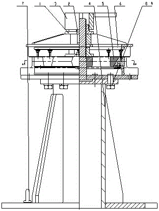
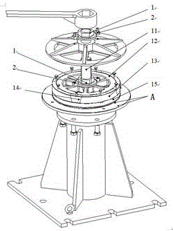
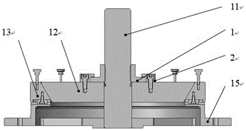
[0023] see Figure 1-4 , a simple internal support fixture for friction stir welding girth seam, including a pressure plate assembly 6, a clamp body 5, and a base assembly 4 for fixing the clamp body 5, the clamp body 5 includes a clamping block, an L-shaped block 3, and a wedge 12 , screw rod 11 and positioning plate 15, the clamping block of the present embodiment includes four main clamping blocks 13 and four secondary clamping blocks 14 arranged uniformly and at intervals, the clamp body 5 is welded with the positioning plate 15 and the screw rod 11 and then The oblique wedge 12, the L-shaped block 3, the main clamping block 13 and the auxiliary clamping block 14 are combined;

[0024] The pressure plate assembly 6 is located above the clamp body 5, the base assembly 4 is located below the clamp body 5, the pressure plate assembly 6 is placed on the clamp body 5, and the screw rod 11 of the clamp body 5 is positioned to ensure that the pressure plate assembly 6 and the wed...


PUM


Abstract

The invention discloses a simple internal bracing clamp for a friction-stir welding circumferential weld and belongs to the technical field of inner bracing clamps for welding. The simple internal bracing clamp for the friction-stir welding circumferential weld comprises a pressing disk assembly, a clamp body and a base assembly used for fixing the clamp body. The pressing disk assembly is located above the clamp body. The base assembly is located below the clamp body. The pressing disk assembly is connected with the clamp body through a threaded rod of the clamp body. Hexagonal head bolts are arranged between the clamp body and the base assembly. A gland nut is arranged at the center of the top of the pressing disk assembly. The clamp body is composed of pre-tightening blocks, L-shaped blocks, a wedge, the threaded rod and a locating disk. The simple internal bracing clamp for the friction-stir welding circumferential weld can effectively and tightly press products and prevent the products from rotating in the movement direction of a stirring pin during welding, and therefore the welding quality is guaranteed; the coaxiality of the welded products can be effectively guaranteed, so that the welding seam dislocation is avoided during butt joint; the situation that because metal is squeezed into a gap of the clamp, the products are difficult to take out after welding can be avoided; and meanwhile, the simple internal bracing clamp for the friction-stir welding circumferential weld further has the advantages of being simple in structure, short in manufacturing period, low in cost and the like.

Description

technical field [0001] The invention relates to a welding inner support fixture, in particular to a simple inner support fixture for friction stir welding circular seam with a horizontally placed stirring head. Background technique [0002] Friction stir welding is a new welding technology. Most of the welding jigs used in it adopt pneumatic structure. Although the degree of automation is high, most of the jigs are due to the low manufacturing precision and structure. The huge pressure exerted by the stirring needle during welding As a result, the semi-fluid metal squeezes into the gap between the fixtures, causing the fixtures to fail to return or the roundness of the inner support is not high, and the clamping and retreating are not coordinated, resulting in uneven weld quality. At the same time, due to the influence of the movement direction of the stirring needle during friction stir welding, the tangential force of the product is very large during welding, and most fixt...

Claims


Application Information

Patent Timeline
Patent Type & Authority Applications(China)
IPC IPC(8): B23K37/04
CPCB23K37/0435
Inventor 刘何荣王彬王向东张新兰
Owner SICHUAN AEROSPACE LONG MARCH EQUIP MFG CO LTD
Why Eureka
Try Eureka