Device and method for controlling a hydraulic machine

A technology for controlling valves and hydraulic pumps, which is applied in the field of hydraulic machinery, can solve the problems of reducing the total efficiency factor of hydraulic machinery, failure to use closed loops, hydraulic energy loss, etc., to achieve increased displacement volume, reliable and stable control, and better control. Effect

Active Publication Date: 2016-11-30
DANFOSS POWER SOLUTIONS GMBH & CO
View PDF7 Cites 4 Cited by
  • Summary
  • Abstract
  • Description
  • Claims
  • Application Information

AI Technical Summary

Problems solved by technology

Additionally, the pressure fluid discharged through the servo displacement unit is usually discharged directly into the tank and thus cannot be used for the preferred closed circuit
Furthermore, this branching of high-pressure fluid from the circuit implies a loss of hydraulic energy
Further losses come from the inevitable leakage in the control system of hydraulic machinery. The higher the pressure of the corresponding control system, the greater the leakage of course
These losses reduce the overall efficiency factor of the hydraulic machinery

Method used


Image

  • Device and method for controlling a hydraulic machine
  • Device and method for controlling a hydraulic machine
  • Device and method for controlling a hydraulic machine

Examples


Embodiment Construction

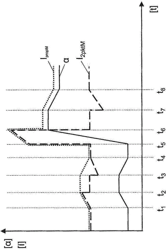
[0031] figure 1 Exemplarily shows the control current I for a proportional controlled hydraulic motor propM Form and give the hydraulic motor with 2-point control and displacement sensor to I 2pktM The form of the timing of the control signal for the actuator. The hydraulic motor is realized, for example, in a bent shaft or swash plate type. The control current controls the control valve to change the displacement angle setting by means of the exemplarily selected actuator of the axial piston hydraulic motor. At time t 1 To t 4 , The adjustment of the displacement angle α is performed for the two hydraulic motors with a relatively low control current and by applying hydraulic fluid from the low-pressure pipeline. According to this, the change runs flat, where at time t 1 And t 2 Between and t 3 To t 4 The displacement angles between them experience rise and fall respectively.

[0032] At time t 5 , A higher control signal is set, so that in addition to the control valve, for e...


PUM


Abstract

The invention relates to a hydraulic machine, in particular to a hydraulic motor with two working lines, from one of which a high pressure line and from the other one a low pressure line is branched off. An electronic control unit and a servo displacement unit are provided to control the displacement of the displacement volume of a drive mechanism of the hydraulic machine, wherein the displacement volume can be determined by the displacement of a servo piston within the servo displacement unit. For this, the servo piston can be loaded at least on one side via a servo pressure line with hydraulic fluid under servo pressure, wherein the servo pressure level can be adjusted by a control spool arranged moveable within a control valve. For this, hydraulic fluid from the low pressure line or, perhaps, from the high pressure line is guidable via the control valve to the servo pressure line if a suitable control signal is available at a switching valve.

Description

Technical field [0001] The present invention relates to hydraulic machines, such as hydraulic motors, which operate by means of two pipelines that conduct hydraulic fluid, in particular by means of a high-pressure pipeline and a low-pressure pipeline. The displacement volume of the drive mechanism of the hydraulic machinery can be adjusted in a controlled manner by means of the control unit, the control valve and the servo displacement unit; thus, the displacement volume can be determined by the displacement of the servo piston in the servo displacement unit. For this purpose, the hydraulic fluid under servo pressure is provided to the servo displacement unit through the servo pressure line and a control plunger arranged in the control valve as movable, so that the servo displacement unit can adjust the displacement of the hydraulic machinery in a controlled manner Volume. Background technique [0002] A general hydraulic machine adjustable in this way is disclosed in DE 3307570...

Claims


Application Information

Patent Timeline
IPC IPC(8): F15B11/02
CPCF15B11/02F15B2211/20546F16H61/421F16H61/423F04B1/34F15B2211/763F16H61/4017F16H61/4026F15B2211/251F15B2211/252
Inventor 苏恩洁·马希伯尔尼·黑姆斯迈克尔·海因安·斯特布劳
Owner DANFOSS POWER SOLUTIONS GMBH & CO
Why Eureka
Try Eureka