
Material guiding mechanism of hook bolt forming machine

A forming machine and bolt technology, applied in the direction of operating devices, metal processing equipment, manufacturing tools, etc., can solve the problems of complex guide structure, inability to ensure material wire and straightening, etc., and achieve the effect of ensuring work quality

Inactive Publication Date: 2016-11-30
新昌县新剡轴承有限公司
View PDF8 Cites 1 Cited by
  • Summary
  • Abstract
  • Description
  • Claims
  • Application Information

AI Technical Summary

Problems solved by technology

[0002] With the continuous improvement of social living standards and the continuous development of science, various mechanical appliances are used in various industries to facilitate life and production. The commonly used hook bolts are used in various industries such as construction furniture because of their convenient processing and flexible use. It is easy to install and use on wooden furniture, and can realize functions such as connection between woods without a large force. When producing hook bolts, generally used mechanical equipment, when processing materials, the material guide mechanism should hold the curved materials. The wire is straightened to ensure the normal processing of the wire, but the structure of the ordinary material guide is relatively complicated, and it is inconvenient to disassemble, and it cannot guarantee that the wire can be straightened.

Method used


Image

  • Material guiding mechanism of hook bolt forming machine
  • Material guiding mechanism of hook bolt forming machine
  • Material guiding mechanism of hook bolt forming machine

Examples


Embodiment Construction

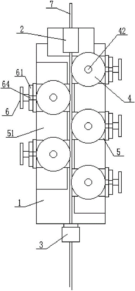
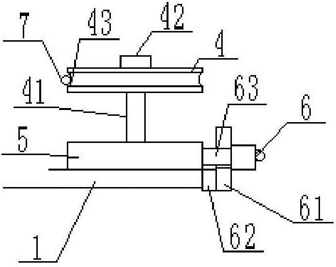
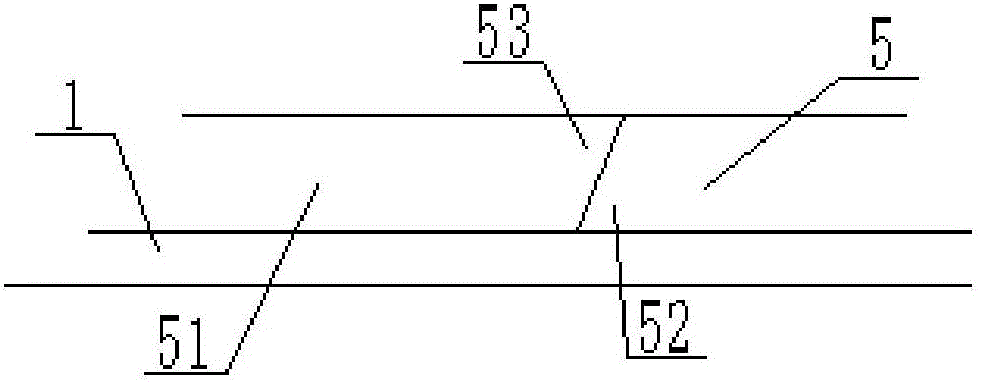
[0014] refer to figure 1 , figure 2 and image 3 , a material guide mechanism of a hook bolt forming machine in the present invention, comprising a bottom plate 1, an upper guide block 2, a lower guide block 3, a guide wheel 4, a mounting plate 5, a handle 6 and a material wire 7, and one end of the bottom plate 1 is installed There is an upper guide block 2, and a lower guide block 3 is installed on the other end of the base plate 1, the upper guide block 2 and the lower guide block 3 are located on the same center line of the base plate 1, and several mounting plates 5 are installed on the upper end of the base plate 1 , the mounting plate 5 is equipped with a wheel shaft 41 and a shaft 63, the wheel shaft 41 is located at the top of the mounting plate 5, the shaft 63 is located at the side of the mounting plate 5, the guide wheel 4 is installed on the wheel shaft 41, the The adjustment handle 6 is installed on the handle shaft 63, and the material wire 7 passes through t...


PUM


Abstract

The invention discloses a material guiding mechanism of a hook bolt forming machine. The material guiding mechanism comprises a bottom plate, an upper guide block, a lower guide block, guide wheels, a plurality of installation plates, adjusting handles and a material wire. The upper guide block is installed at one end of the bottom plate, the lower guide block is installed at the other end of the bottom plate, the upper guide block and the lower guide block are located on the same central line of the bottom plate, the installation plates are further installed at the upper end of the bottom plate, wheel shafts and handle shafts are installed on the installation plates, the wheel shafts are located on the tops of the installation plates, the handle shafts are located on the side faces of the installation plates, the guide wheels are installed on the wheel shafts, the adjusting handles are installed on the handle shafts, the material wire penetrates through the upper guide block and the lower guide block to be in fit contact with the guide wheels, and fixing plates are distributed on the opposite sides of the bottom plate in a spaced mode. By means of the material guiding mechanism of the hook bolt forming machine, the material wire can be well guided to be straight, and the working quality can be ensured; meanwhile, the installation and maintenance efficiency is improved due to the simple structure.

Description

【Technical field】 [0001] The invention relates to the technical field of hook bolt processing machinery, in particular to the technical field of a material guide mechanism of a hook bolt forming machine. 【Background technique】 [0002] With the continuous improvement of social living standards and the continuous development of science, various mechanical appliances are used in various industries to facilitate life and production. The hook bolts commonly used are used in various industries such as construction furniture because of their convenient processing and flexible use. It is easy to install and use on wooden furniture, and can realize functions such as connection between wood without a large force. When producing hook bolts, it is generally used in mechanical equipment. When processing materials, the material guide mechanism should be bent. The wire is straightened to ensure the normal processing of the material wire, but the ordinary material guide structure is relati...

Claims


Application Information

Patent Timeline
Patent Type & Authority Applications(China)
IPC IPC(8): B21K27/00
CPCB21K27/00
Inventor 俞宝珍
Owner 新昌县新剡轴承有限公司
Learn More