Light emitting diode driving circuit and light emitting diode lighting device

A technology of light-emitting diodes and driving circuits, applied in electroluminescent light sources, lighting devices, lamp circuit layout, etc., can solve the problems of low working efficiency and high cost of driving circuits, and achieve good ECG compatibility, high power factor, and flexible topology structure effect

Active Publication Date: 2016-11-23
LEDVANCE GMBH
View PDF4 Cites 5 Cited by
  • Summary
  • Abstract
  • Description
  • Claims
  • Application Information

AI Technical Summary

Problems solved by technology

[0005] Currently, in the prior art, a drive circuit of a two-stage converter with a step-up power factor correction (PFC) converter and a buck converter is used to be compatible with AC mains, CCG, and ECG, but the two-stage converter The drive circuit has low efficiency and high cost

Method used


Image

  • Light emitting diode driving circuit and light emitting diode lighting device
  • Light emitting diode driving circuit and light emitting diode lighting device
  • Light emitting diode driving circuit and light emitting diode lighting device

Examples


Embodiment Construction

[0029] The present invention will be described below with reference to block diagrams, circuit diagrams, etc. of the device according to the embodiments of the present invention. It should be noted that, for the purpose of clarity, representations and descriptions of components and processes that are not related to the present invention and known to those of ordinary skill in the art are omitted from the drawings and descriptions. The terms used herein are only for describing specific embodiments, and are not intended to limit the present invention.

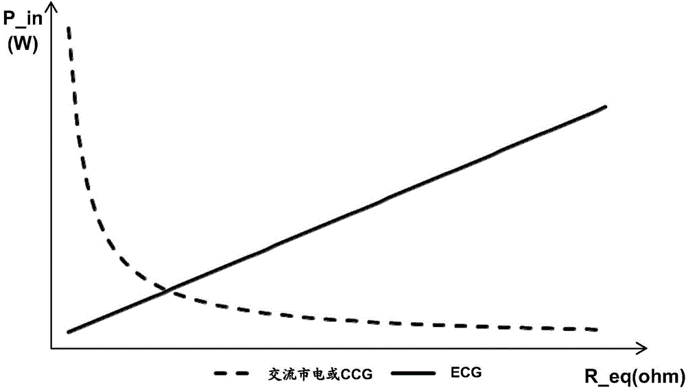
[0030] First, briefly describe the general relationship between the equivalent input impedance of the LED drive circuit and the input power. figure 1 It is a graph illustrating the relationship between the equivalent input impedance of the drive circuit and the input power when the LED drive circuit is powered by AC mains or CCG and ECG.

[0031] Specifically, AC mains and CCG can be approximately regarded as low-frequency constant vo...


PUM


Abstract

The application relates to a light emitting diode driving circuit and a light emitting diode lighting device. The light emitting diode (LED) driving circuit comprises a detection circuit, a first-level converter, a first feedback loop, and a second feedback loop. The detection circuit detects whether the input of the driving circuit is low-frequency current or high-frequency current. The first-level converter converts the input of the driving circuit, and provides DC power suitable for LED. The first feedback loop is activated when the detection circuit detects that the input of the driving circuit is low-frequency current, the first feedback loop converts the current of an LED load into a feedback voltage and feeds back the feedback voltage to the first-level converter, the feedback voltage decreases when the current of the LED load is greater than a target value, and the feedback voltage increases when the current of the LED load is smaller than the target value. The second feedback loop is activated when the detection circuit detects that the input of the driving circuit is high-frequency current, the second feedback loop converts the current of the LED load into a feedback voltage and feeds back the feedback voltage to the first-level converter, the feedback voltage increases when the current of the LED load is greater than the target value, and the feedback voltage decreases when the current of the LED load is smaller than the target value.

Description

Technical field [0001] The present invention relates to the field of lighting driving, in particular to a light-emitting diode driving circuit and light-emitting diode lighting equipment compatible with AC mains (ACmains), traditional ballasts (CCG) and electronic ballasts (ECG). Background technique [0002] With the rise and continuous improvement of solid-state lighting technology, light-emitting diodes (LEDs) have become the preferred solution for today's lighting projects due to their high efficiency, energy saving, long life, and environmental protection, and are gradually being used in lighting products. A key factor that makes people pay attention to LED lighting technology is that it greatly reduces energy consumption and can achieve long-term reliable work. [0003] The LED tube is driven by DC. Whether it is powered by AC mains or CCG or ECG, a power adapter is required between AC mains, CCG and ECG and the LED, that is, an LED drive circuit. Its function is to convert ...

Claims


Application Information

Patent Timeline
Patent Type & Authority Applications(China)
IPC IPC(8): H05B37/02H05B44/00
CPCH05B47/10H05B45/38H05B45/3725H05B45/375
Inventor 杨旭生黄凯纯
Owner LEDVANCE GMBH
Why Eureka
Try Eureka