
Self-excited piezoelectric energy harvesting device for river monitoring

A piezoelectric energy harvesting and self-excitation technology, which is applied to piezoelectric effect/electrostrictive or magnetostrictive motors, electrical components, electromechanical devices, etc., can solve the problem of large-scale application and monitoring system power supply. The problem has not been well solved and other problems, to achieve the effect of simple structure, strong flow rate adaptability and high reliability

Active Publication Date: 2016-11-23
常州昂德工业装备科技有限公司
View PDF6 Cites 10 Cited by
  • Summary
  • Abstract
  • Description
  • Claims
  • Application Information

AI Technical Summary

Problems solved by technology

Although some of the proposed monitoring methods are relatively mature at the technical level, they have not been popularized and applied on a large scale. One of the main reasons is that the power supply problem of the monitoring system has not been well resolved.

Method used


Image

  • Self-excited piezoelectric energy harvesting device for river monitoring
  • Self-excited piezoelectric energy harvesting device for river monitoring
  • Self-excited piezoelectric energy harvesting device for river monitoring

Examples


Embodiment Construction

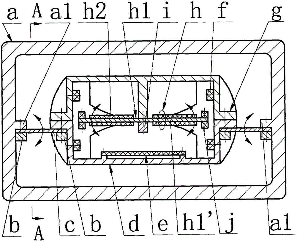
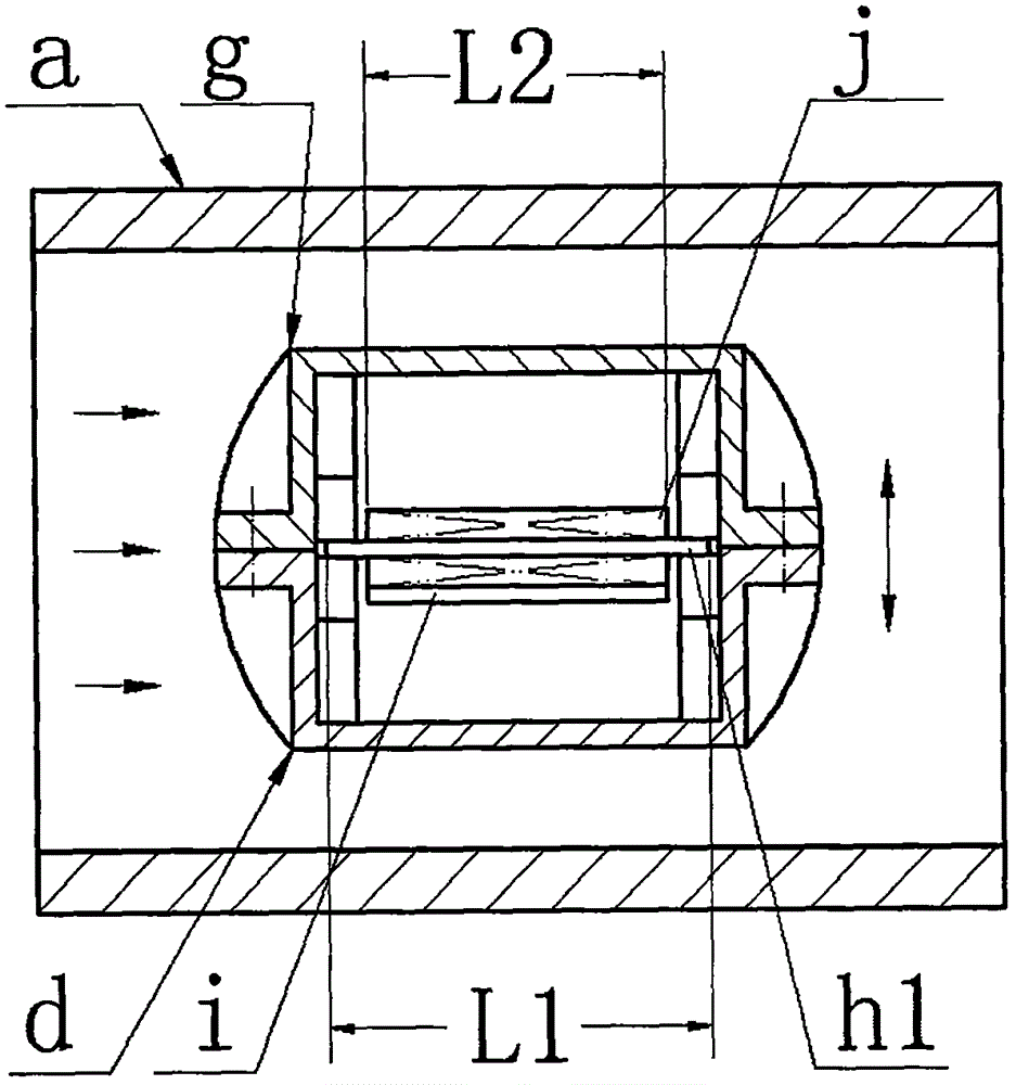
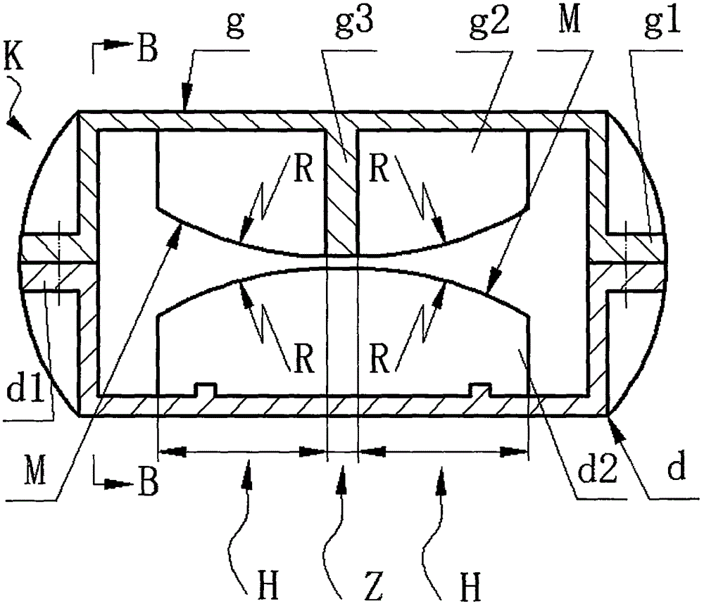
[0011] Two connecting ears a1 are symmetrically arranged on the inner wall of the pipe a, and a reed c is installed on the two connecting ears through screws and a pressure plate b. The plane of the reed c is parallel to the symmetrical center line of the pipe a; the upper half shell g The flange g1 and the flange d1 of the lower half-shell d are connected by screws, and the connected upper half-shell g and the lower half-shell d form a closed shell K; the flange g1 of the upper half-shell g or the method of the lower half-shell d Lan d1 is connected to the two reeds c via screws and pressure plate b; upper bosses g2 are provided on the front and rear side walls of the upper half shell g, and lower bosses are provided on the front and rear side walls of the lower half shell d d2, a partition g3 is provided at the symmetrical center of the two upper bosses g2; a limit surface M is provided on the upper boss g2 and the lower boss d2, and the limit surface M is composed of a strai...


PUM


Abstract

The invention relates to a self-excited piezoelectric energy harvesting device for river monitoring and belongs to the field of river monitoring. The self-excited piezoelectric energy harvesting device is characterized in that two connecting lugs are arranged on the inner wall of a pipeline; a reed is mounted on each of the connecting lugs, and a plane of the reed is parallel to a symmetric center line of the pipeline; an upper half shell and a lower half shell are connected through flanges and form a closed shell; the flange of the upper half shell or the flange of the lower half shell is connected with the two reeds; an upper boss is arranged on each of the front side wall and the rear side wall of the upper half shell, a lower boss is arranged on each of the front side wall and the rear side wall of the lower half shell, and a partition plate is arranged at the symmetric center of the two upper bosses; a limiting surface is composed of a straight section and two circular arc sections and is arranged on each of the upper bosses and the lower bosses, and the straight section is equal to the partition plate in width; a metal substrate is fixed on the partition plate through a pressing block and forms two metal cantilever beams, a coil is mounted at the free end of each of the metal cantilever beams, a piezoelectric wafer is bonded on the side surface of the metal cantilever beam, and the metal cantilever beam and the bonded piezoelectric wafer form a piezoelectric vibrator. The self-excited piezoelectric energy harvesting device provided by the invention has the advantages of being simple in structure, strong in flow rate adaptability, wide in effective frequency band, high in reliability and strong in power generation capacity.

Description

technical field [0001] The invention belongs to the technical field of river monitoring, in particular to a self-excited piezoelectric energy harvester for river monitoring, which is used to construct a self-powered river monitoring system. Background technique [0002] There are thousands of rivers all over the territory of our country. In recent years, due to insufficient treatment of industrial waste water, soil erosion, improper use of pesticides and chemical fertilizers, etc., most rivers have been polluted to a certain extent. Nearly a quarter of the rivers or river sections cannot meet the basic requirements due to pollution. Irrigation needs; in addition, because the flood control facilities of small and medium-sized rivers in many areas are not perfect, or even do not have any flood control facilities, when the flood season comes, it may cause dangers such as embankment failure or flooding, which directly threatens the lives and property safety of the people along t...

Claims


Application Information

Patent Timeline
IPC IPC(8): H02N2/18H02K35/02
CPCH02K35/02H02N2/185
Inventor 温建明阚君武程光明王淑云郭健安
Owner 常州昂德工业装备科技有限公司
Learn More