Radial vibration piezoelectric ceramic transformer with multiple output ends
A piezoelectric ceramic and radial vibration technology, applied in the field of transformers, can solve the problem of inability to generate multiple different output voltages, and achieve the effect of improving the heating problem and realizing the resonance frequency.
- Summary
- Abstract
- Description
- Claims
- Application Information
AI Technical Summary
Problems solved by technology
Method used
Image

Examples
Embodiment 1
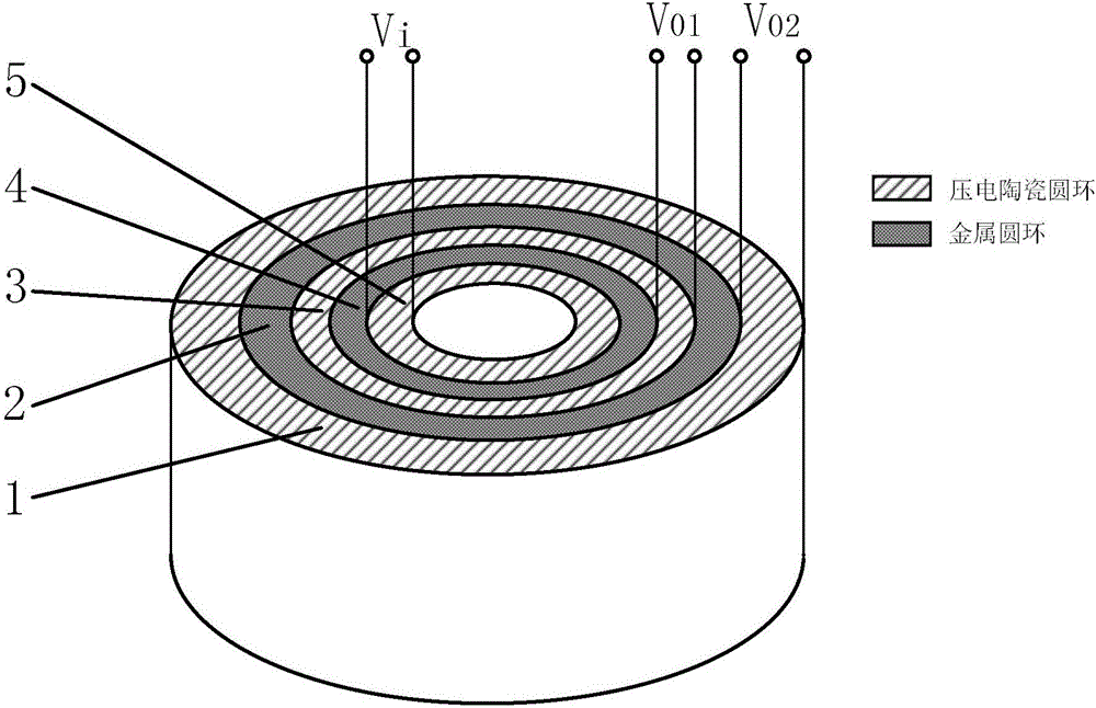
[0023] Such as figure 1 As shown, the structural diagram of the radially vibrating piezoelectric ceramic transformer with multiple output terminals of the present invention is composed of multiple piezoelectric ceramic rings and metal rings compounded in the radial direction, wherein two adjacent piezoelectric ceramic A metal ring is arranged between the rings, any one of the piezoelectric ceramic rings is selected as an input end, and each of the other piezoelectric ceramic rings constitutes an output end respectively, and the inner and outer cylindrical surfaces of the piezoelectric ceramic rings are Both are plated with silver electrodes and polarized in the radial direction. The axial height of the piezoelectric ceramic ring is equal to that of the metal ring, and the upper and lower end faces are in the same plane. The axial height is less than the maximum diameter of the piezoelectric ceramic ring. one fifth.
[0024] The present invention adopts the composite of multi-...
Embodiment 2
[0026] On the basis of Embodiment 1, the piezoceramic rings are all made of emissive piezoceramic materials with high piezoelectric coefficients, such as PZT-4 or PZT-8, which require low dielectric loss and mechanical loss of the material, Good elasticity, high electromechanical conversion coefficient, high Curie temperature, and high temperature stability; the metal ring is made of any material such as aluminum alloy, aluminum-magnesium alloy, titanium alloy, and copper. The material is required to have good elasticity, low loss, and vibration Good transmission performance and strong heat transfer performance to increase the heat dissipation performance of the transformer.
[0027] The piezoelectric ceramic ring and the metal ring are bonded by high-strength glue, or by strictly controlling the size of the piezoelectric ceramic ring and the metal ring, and making use of the thermal expansion and contraction characteristics of different materials to make each part tightly com...
Embodiment 3
[0029] On the basis of the above examples, if figure 1 As shown, the figure shows a piezoelectric ceramic transformer composed of three piezoelectric ceramic rings and two metal rings. From the outside to the inside, the output piezoelectric ring 2 1, the metal ring 2 , and the output Piezoelectric ring one 3, metal ring one 4 and input piezoelectric ring 5.
[0030] When an alternating voltage Vi is applied to the inner and outer surfaces of the input piezoelectric ring 5 of the piezoelectric transformer, the piezoelectric transformer will generate mechanical vibration by virtue of the inverse piezoelectric effect. When the driving voltage frequency of the piezoelectric ceramic transformer is equal to the resonance frequency of the piezoelectric ceramic transformer, the mechanical vibration of the transformer reaches the maximum. At this time, the input power and efficiency of the transformer reach the maximum, and the piezoelectric ceramic transformer should work at its reso...
PUM
| Property | Measurement | Unit |
|---|---|---|
| thickness | aaaaa | aaaaa |
Abstract
Description
Claims
Application Information
 - Generate Ideas
- Intellectual Property
- Life Sciences
- Materials
- Tech Scout
- Unparalleled Data Quality
- Higher Quality Content
- 60% Fewer Hallucinations
Browse by: Latest US Patents, China's latest patents, Technical Efficacy Thesaurus, Application Domain, Technology Topic, Popular Technical Reports.
© 2025 PatSnap. All rights reserved.Legal|Privacy policy|Modern Slavery Act Transparency Statement|Sitemap|About US| Contact US: help@patsnap.com