Restructuring method of processing box and restructured processing box

A process cartridge and installation direction technology, applied in the field of remanufacturing methods and remanufactured process cartridges, can solve the problem that the process cartridge cannot be taken out smoothly for the driving member

Active Publication Date: 2016-11-23
NINESTAR CORP
View PDF3 Cites 7 Cited by
  • Summary
  • Abstract
  • Description
  • Claims
  • Application Information

AI Technical Summary

Problems solved by technology

[0003] The invention provides a process box modification method to solve the technical problem that the process box cannot be taken out smoothly because it is difficult to make the drive member axially retract and disengage from the engagement of the drive part in the existing process box

Method used


Image

  • Restructuring method of processing box and restructured processing box
  • Restructuring method of processing box and restructured processing box
  • Restructuring method of processing box and restructured processing box

Examples


Embodiment 1

[0038] Please refer to Figure 1-Figure 6 , the present embodiment provides a method for remanufacturing a process cartridge and the remanufactured process cartridge obtained thereby, so that the process cartridge can be easily disassembled from the imaging device.

[0039] (The structure of the treatment box before modification)

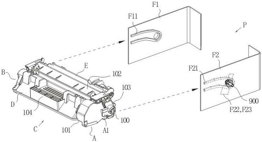
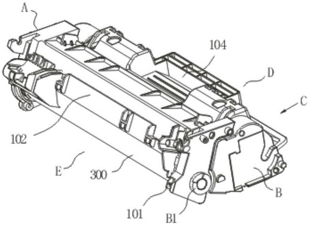
[0040] Such as Figure 1-Figure 3 As shown, the process cartridge C before remanufacturing includes: a housing 101, a driving end A and a conductive end B located on both lateral sides of the housing, and a front end E facing the installation direction and a rear end D facing the pulling direction. The housing 101 includes a waste toner bin 102 and a drum bracket 103. The drum bracket 103 is arranged at the driving end of the waste toner bin 102 for supporting the photosensitive element 300 and the photosensitive element arranged in the waste toner bin. The drive member 100 at the end of the drive end rotates.

[0041] Such as Figure 4 As shown...

Embodiment 2

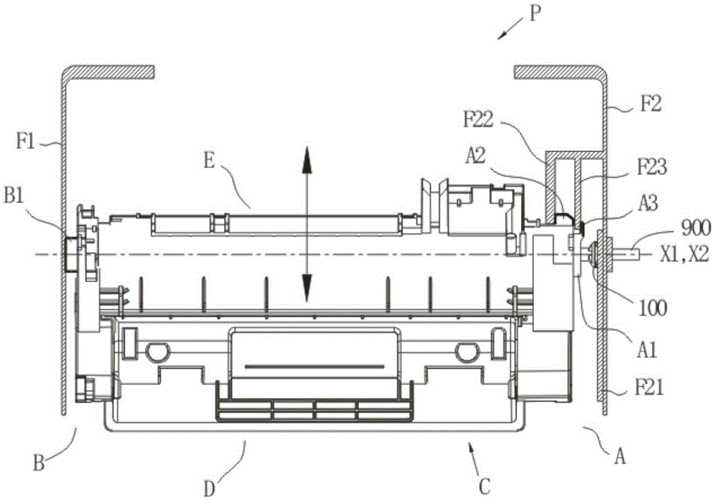
[0056] Please refer to Figure 5 as well as Figure 8-Figure 10a , the present embodiment provides a method for remanufacturing a process cartridge and the resulting remanufactured process cartridge. On the basis of the structure of the process cartridge in Embodiment 1, a limiter is further added at the driving end A of the process cartridge toward the front end E. The position avoidance part is a telescopic member that can expand and contract relative to the surface of the process cartridge housing where it is located, or an elastic member that can undergo elastic deformation such as a rubber stopper. After the process box is installed in the image forming device, the position avoidance part can be inserted into the gap between the first limiting rib F22 and the second limiting rib F23, or can be inserted into the second limiting rib F23 and the second limiting rib F23. In the gap between the right side wall F2, to prevent the process box from vibrating and shifting during ...


PUM


Abstract

The invention relates to a restructuring method of a processing box and a restructured processing box. The processing box is detachably installed in an imaging device with installation direction while the processing box has removal direction when removed from the imaging device. The restructuring method includes the following steps of 1), restructuring a first supporting portion of the conductive side of the shell of the processing box to obtain at least one avoiding guide surface which enables the removal direction of the processing box removed from the imaging device to generate inclination relative to the installation direction of the processing box; 2), restructuring limit portions arranged at the driving end of the processing box and arranged at the front end of the shell of the processing box relative to the installation direction of the processing box to remove the interference structure hindering inclination. The technical problem that an existing processing box can hardly enable a driving component to retract axially to be separated from occlusion of a driving portion resulting in the fact that the processing box cannot be removed smoothly is solved.

Description

technical field [0001] The invention relates to image forming equipment technology, in particular to a process box remanufacturing method and the remanufactured process box. Background technique [0002] Laser printers, photocopiers, facsimile machines and other electronic imaging devices are detachably installed with processing boxes for imaging, such as figure 1 with image 3 As shown, there are guide rails F11 and F21 on the left and right side walls F1 and F2 of the imaging device P respectively, and the conductive end and the driving end of the process box C slide into the imaging device P along the guide rails F11 and F21 respectively, and pass through the process box C The driving member 100 on the driving end is engaged with the driving part 900 of the imaging device P to transmit the rotational force output from the imaging device P to drive the photosensitive element and other components in the process cartridge to rotate. The used driving member of the process c...

Claims


Application Information

Patent Timeline
Patent Type & Authority Applications(China)
IPC IPC(8): G03G21/18
Inventor 不公告发明人
Owner NINESTAR CORP
Why Eureka
Try Eureka