Fault detection device and method applied to high-tension battery contactor
A high-voltage battery, fault detection technology, applied in circuit breaker testing and other directions, can solve problems such as increasing fault detection time, prolonging the startup time of related equipment, etc., to achieve the effect of fast detection speed, excellent implementation effect, and simple structure setting.
- Summary
- Abstract
- Description
- Claims
- Application Information
AI Technical Summary
Problems solved by technology
Method used
Image
Examples
Embodiment approach
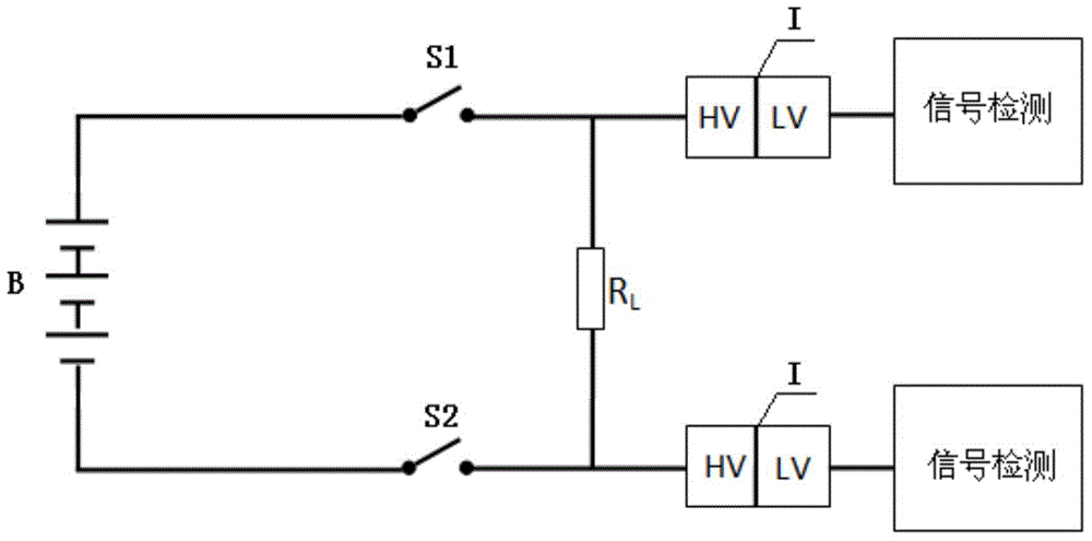
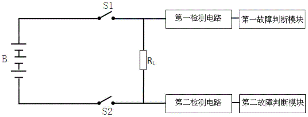
[0058] It should be noted that, according to the needs of practical applications, those skilled in the art may also connect the output terminals of the first detection circuit and the output terminal of the second detection circuit to the same fault judgment module respectively. In this embodiment, the two detection circuits respectively corresponding to the positive contactor S1 and the negative contactor S2 are connected to the same fault judgment module, and the fault judgment module receives signals from the two detection circuits respectively, and at the same time realizes positive contact Judgment and detection of faults in S1 and negative contactor S2.
[0059] image 3 A schematic block diagram of a detection circuit of a fault detection device applied to a high-voltage battery contactor according to the present invention is shown in an implementation manner. In this embodiment, the detection circuit includes: a signal conversion module, whose input terminal receives ...
Embodiment 1
[0063] Figure 5 It shows the circuit diagram of the detection circuit in the first embodiment of the fault detection device applied to the high-voltage battery contactor according to the present invention. Such as Figure 5 As shown, in this embodiment, the detection circuit includes a first detection circuit for detecting the positive contactor S1 and a second detection circuit for detecting the negative contactor S2. The first detection circuit includes: a first photocoupler T1, a voltage dividing resistor R1, a voltage dividing resistor R3 and a resistor R5; wherein, the positive input terminal of the first photocoupler T1 is connected to one end of the first protection module through the voltage dividing resistor R1 connected, and with the positive contactor S1 as well as the load R L One end of the first optocoupler T1 is connected to the negative input terminal of the first protection module through the voltage dividing resistor R3, and is connected to the negative po...
Embodiment 2
[0072] Figure 6 It shows the circuit diagram of the detection circuit in the second embodiment of the fault detection device applied to the high-voltage battery contactor according to the present invention. Such as Figure 6 As shown, in this embodiment, the first detection circuit includes: a first photocoupler T1, a voltage dividing resistor R1, a voltage dividing resistor R3 and a resistor R5; wherein, the positive input terminal of the first photocoupler T1 is divided by Resistor R1 is connected to one end of the first protection module, and is connected to positive contactor S1 and load R L One end of the first optocoupler T1 is connected to the negative input terminal of the first protection module through the voltage dividing resistor R3, and is connected to the negative pole of the high-voltage battery B; the collector of the phototransistor of the first optocoupler T1 As the first output end, it is connected to the positive pole of the low-voltage power supply +5V,...
PUM
 Abstract
Description
Claims
Application Information
 - R&D
- Intellectual Property
- Life Sciences
- Materials
- Tech Scout
- Unparalleled Data Quality
- Higher Quality Content
- 60% Fewer Hallucinations
Browse by: Latest US Patents, China's latest patents, Technical Efficacy Thesaurus, Application Domain, Technology Topic, Popular Technical Reports.
© 2025 PatSnap. All rights reserved.Legal|Privacy policy|Modern Slavery Act Transparency Statement|Sitemap|About US| Contact US: help@patsnap.com


