Injection molding machine and glue melting threaded rod thereof

A molding machine and glue melting technology, applied in the field of injection molding machine and its glue melting screw, can solve the problems of not being able to obtain excellent comprehensive performance, and achieve the effects of improving solid-phase heat exchange, stable output and stable pressure

Active Publication Date: 2016-11-23
震雄机械(深圳)有限公司
View PDF4 Cites 1 Cited by
  • Summary
  • Abstract
  • Description
  • Claims
  • Application Information

AI Technical Summary

Problems solved by technology

[0010] The present invention proposes an injection molding machine and its melt-glue screw, which solves the problem that the traditional single-thread melt-glue screw and several commonly used or variable-pitch, barrier or separate screws cannot completely solve the problem of production efficiency and plasticizing effect in the prior art. And temperature rise and other properties, and the problem of not being able to obtain excellent comprehensive performance, makes the melt glue screw of the injection molding machine of the present invention have wider adaptability

Method used


Image

  • Injection molding machine and glue melting threaded rod thereof
  • Injection molding machine and glue melting threaded rod thereof
  • Injection molding machine and glue melting threaded rod thereof

Examples


Embodiment Construction

[0041] In order to further illustrate the principle and structure of the present invention, preferred embodiments of the present invention will now be described in detail with reference to the accompanying drawings.

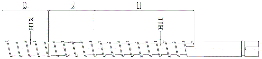
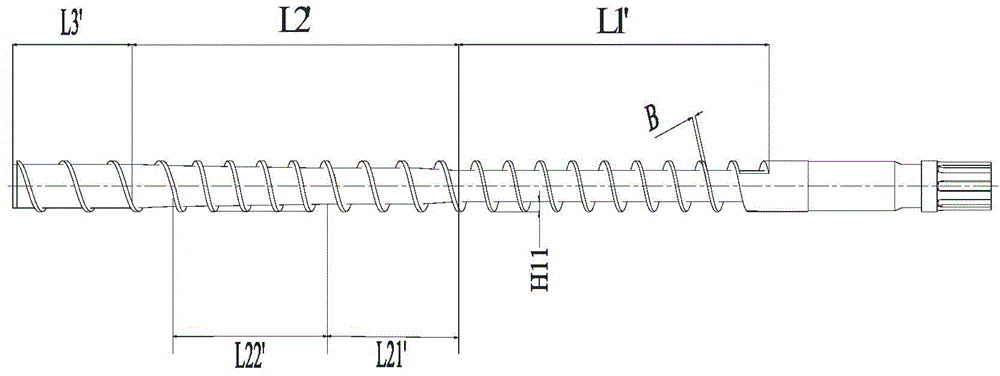
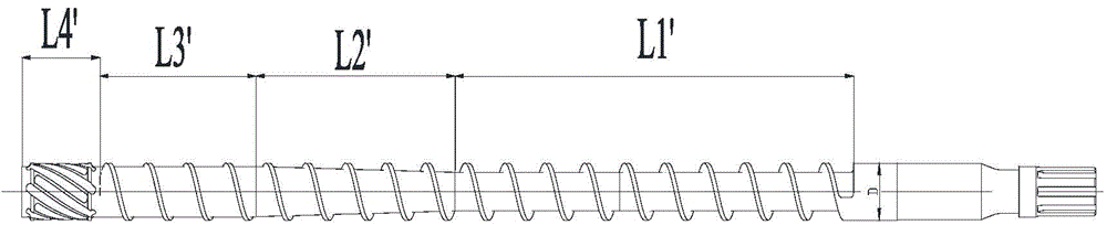
[0042] refer to Figure 7 to Figure 11 , the present invention provides an injection molding machine 100, which includes a plastic injection part 1, the plastic injection part 1 includes a material tube set 2, the material tube set 2 includes a melt glue screw 3, and the melt glue screw 3 is used for The plastic is plasticized into a melt in the injection molding machine 100 . The melt glue screw 3 is connected with the driving motor 8 through the transmission system 9, and the other end is equipped with three small parts of the check valve, which include the screw head 4, the non-return ring 5 and the thrust washer 6.

[0043] The glue screw 3 includes a threaded portion 31 and a coupling portion 32 connected to each other. The coupling part 32 includes a coup...


PUM


Abstract

The invention provides an injection molding machine and a glue melting threaded rod thereof. A thread part of the glue melting threaded rod comprises a feeding section and a plasticizing section. The plasticizing section is composed of four different variable-diameter and variable-distance compression sections. The whole glue melting threaded rod is provided with auxiliary external thread screw flights as barriers. A main external threaded groove of the plasticizing section is divided into a solid phase groove and a liquid phase groove, the solid phase groove gets shallower gradually, and the liquid phase groove gets deeper gradually. When plastic enters from the feeding section to the solid phase groove, after the solid phase groove is gently compressed and plasticized, a melt crosses gaps of the auxiliary external thread screw flights to be sheared and plasticized sufficiently, enters the variable-distance large-pitch liquid phase groove, and then is delivered into a storage space of a charging barrel in a small-damp and high-efficiency mode. Meanwhile, a vortex is formed, vortex flowing along the section of the liquid phase groove is generated, the melt is uniformly mixed, heat exchange between the melt and the charging barrel is more sufficient, and the uniform-temperature high-quality melt is generated. The injection molding machine is stable in production process, and both the plasticizing capacity and the melt quality are improved.

Description

technical field [0001] The invention relates to molding equipment, in particular to an injection molding machine and its melt screw. Background technique [0002] At present, the commonly used melt glue screw is the traditional three-stage single-flight screw, the general-purpose variable-pitch screw, the barrier-type high-mixing screw, and the separation-type double-flight screw. [0003] Such as figure 1 As shown, it is a traditional three-section single-flight screw. The three-section single-flight screw includes a threaded part and a connecting part, and the threaded part includes a feed section L1', a compression section L2' and a homogenization section L3'. The feed section L1' is formed by the external thread with a straight root with a depth of H11, the compression section L2 is composed of an external thread with an inclined root, and the homogenizing section L3 is composed of an external thread with a straight root with a depth of H12. Its working principle is: ...

Claims


Application Information

Patent Timeline
Patent Type & Authority Applications(China)
IPC IPC(8): B29C45/60
CPCB29C45/60B29C2045/605
Inventor 蒋志坚王海平
Owner 震雄机械(深圳)有限公司
Why Eureka
Try Eureka