Injection mold and control system and method for controlling mold cavity pressure
An injection mold and control system technology, applied in the field of injection mold cavity pressure control, can solve the problem that the pressure uniformity of the last filled area of the melt and the melt filled area cannot be guaranteed, and achieve uniform cavity pressure control and stable air pressure. And accurate, to achieve the effect of multi-level adjustment
- Summary
- Abstract
- Description
- Claims
- Application Information
AI Technical Summary
Problems solved by technology
Method used
Image

Examples
Embodiment 1
[0066] The working process of the gas back pressure assisted injection molding process is:
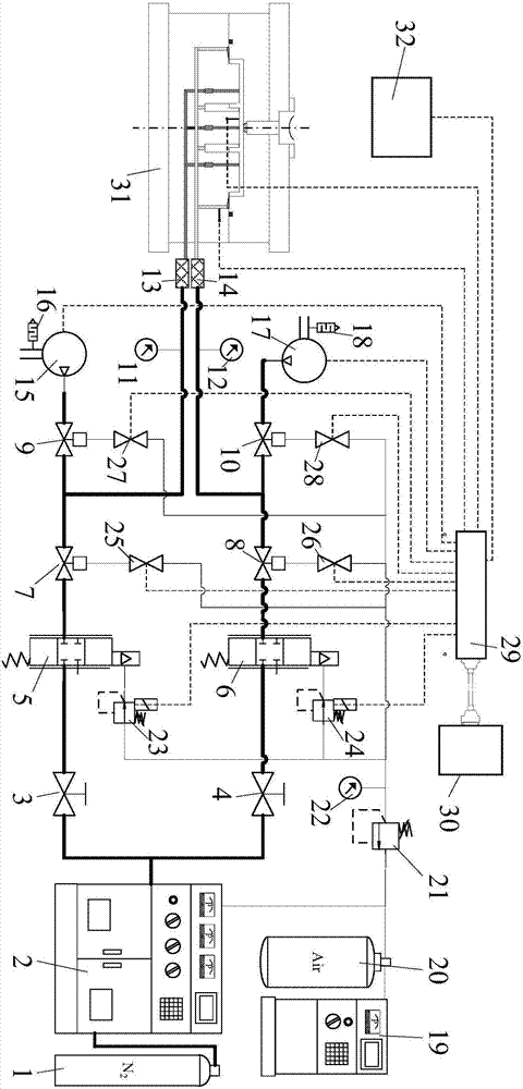
[0067] Step (1), before the device starts to work, open the second manual shut-off valve 4, close the first manual shut-off valve 3, when the pressure booster 2 raises the pressure of the nitrogen source 1 to a certain value within the range of 15-20 MPa , the PLC module 29 sends signals to all solenoid valves and vacuum pumps to close all pneumatic shut-off valves and vacuum pumps.
[0068] In step (2), the PLC module 29 receives the mold clamping end signal from the injection molding machine control system 32 , sends a signal to the second solenoid valve 26 , and opens the second pneumatic shut-off valve 8 . The high-pressure gas flows out from the pressurization device 2, passes through the second manual stop valve 4, the second air-operated pressure reducing valve 6, the second pneumatic stop valve 8, the second pressure gauge 12, and the second filter 14, and enters the edge of th...
Embodiment 2
[0072] Embodiment 2: The working process of the external gas-assisted injection molding process is:
[0073] Step (1), before the device starts to work, open the first manual shut-off valve 3, close the second manual shut-off valve 4, when the pressure booster 2 raises the pressure of the nitrogen source 1 to a certain value within the range of 15-30MPa , the PLC module 29 sends signals to all solenoid valves and vacuum pumps to close all pneumatic shut-off valves and vacuum pumps.
[0074] In step (2), the PLC module 29 receives the signal of injection completion from the injection molding machine control system 32, sends signals to the first solenoid valve 25 and the fourth solenoid valve 28, and opens the first pneumatic shut-off valve 7 and the fourth pneumatic shut-off valve 10 . The high-pressure gas flows out from the pressurization device 2, passes through the first manual stop valve 3, the first air-operated pressure reducing valve 5, the first pneumatic stop valve 7,...
Embodiment 3
[0079] The working process of the short-shot microcellular foaming injection molding process is:
[0080] Step (1), before the device starts to work, open the first manual shut-off valve 3 and the second manual shut-off valve 4, when the pressurization device 2 raises the pressure of the nitrogen source 1 to a certain value within the range of 15-30MPa, The PLC module 29 sends signals to all solenoid valves and vacuum pumps to close all pneumatic stop valves and vacuum pumps.
[0081] In step (2), the PLC module 29 receives the signal from the control system 32 of the injection molding machine that mold closing is completed, sends signals to the first solenoid valve 25 and the second solenoid valve 26, and opens the first pneumatic shut-off valve 7 and the second pneumatic shut-off valve 8 . The high-pressure gas flows out from the booster device 2 and enters the mold cavity 47 in two ways. All the way through the first manual cut-off valve 3, the first air-controlled pressur...
PUM
 Abstract
Description
Claims
Application Information
 - R&D
- Intellectual Property
- Life Sciences
- Materials
- Tech Scout
- Unparalleled Data Quality
- Higher Quality Content
- 60% Fewer Hallucinations
Browse by: Latest US Patents, China's latest patents, Technical Efficacy Thesaurus, Application Domain, Technology Topic, Popular Technical Reports.
© 2025 PatSnap. All rights reserved.Legal|Privacy policy|Modern Slavery Act Transparency Statement|Sitemap|About US| Contact US: help@patsnap.com