Drum type sand mixer and sand mixing method thereof
A sand mixer and drum-type technology, which is applied in the cleaning/processing machinery of casting mold materials, casting molding equipment, metal processing equipment, etc., can solve the problem of difficulty in accurately controlling the humidity of sand materials, poor sand mixing quality, and easy loss of auxiliary materials To achieve the effect of improving sand mixing uniformity, good force, and reducing material transportation
- Summary
- Abstract
- Description
- Claims
- Application Information
AI Technical Summary
Problems solved by technology
Method used
Image


Examples
Embodiment 1
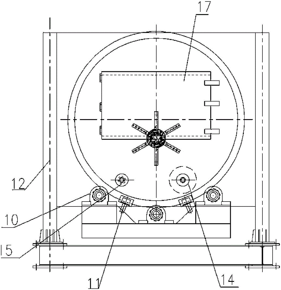
[0044] Such as figure 2 , 3As shown, the sand mixer provided in this embodiment includes a drum 1, which is arranged axially and laterally on the base 2, and the upper part of the side wall of the end face of the drum 1 is provided with a sand material inlet 3 and an auxiliary material inlet 4. The lower part of the side wall of the end face is provided with a discharge port 5 . The upper part of the end face side wall of the drum 1 is also provided with a water inlet 6, and the water inlet 6 is used to add water to the drum to achieve the target humidity. Moreover, the drum 1 in this embodiment is provided with an airtight casing 12 , and a vacuum tube 13 is arranged on the airtight casing 12 , and the vacuum tube 13 is used to extract the gas in the airtight casing 12 . Wherein, the airtight casing 12 can be made of metal material, and those skilled in the art can select the airtight casing of a suitable material according to needs, so that it can meet the requirements of...
Embodiment 2
[0053] This embodiment is a preferred embodiment of Embodiment 1, except for the following differences, the rest of the structure is the same as Embodiment 1. details as follows:
[0054] Such as Figure 4 , 5 As shown, the drum 1 in this embodiment also includes a rolling wheel 14, which can be one or more, and the rolling wheel 14 is arranged between the rotor 7 and the side wall of the drum 1 and is arranged in parallel with the rotor 7. Wheel 14 links to each other with roller drive, and roller 14 rotates under the drive of roller drive. When there are multiple rolling wheels, one of the rolling wheels can be set at the bottom of the drum to realize the rolling and moving functions of the rolling wheels.
[0055] The rotation direction of the rolling wheel 14 in this embodiment is opposite to that of the rotor 7, so that the mixing effect of the sand material is better.
[0056] The side of the rotor 7 in this embodiment is also evenly provided with several scraper mec...
Embodiment 3
[0060] In this embodiment, except that the following parts are different from the above-mentioned embodiment, all the others adopt the same implementation mode as the above-mentioned embodiment, as follows:
[0061] In the drum in the present embodiment, only the roller 14 is used to stir the sand, and there can be one or more rollers. The roller 14 is arranged in the drum and is parallel to the axis of the drum. The drive is connected, and the rolling wheel 14 rotates under the driving of the rolling wheel drive. The sand mixer provided in this embodiment is not provided with a rotor mechanism. When sand mixing is required, the sand mixing is carried out by rollers, and dry mixing or wet mixing can be carried out in conjunction with the rotation of the drum. The roller type sand mixer has good sand mixing quality and sufficient rolling.
PUM
 Abstract
Description
Claims
Application Information
 - R&D
- Intellectual Property
- Life Sciences
- Materials
- Tech Scout
- Unparalleled Data Quality
- Higher Quality Content
- 60% Fewer Hallucinations
Browse by: Latest US Patents, China's latest patents, Technical Efficacy Thesaurus, Application Domain, Technology Topic, Popular Technical Reports.
© 2025 PatSnap. All rights reserved.Legal|Privacy policy|Modern Slavery Act Transparency Statement|Sitemap|About US| Contact US: help@patsnap.com